


256 Run Light (8bit Bin Up-Down)
#8-bit counter
#binary decoder
#run light
#up-down counter
#LED display
#digital circuit
#binary logic
#sequential logic

Description: This is an 8-bit up/down counter that, together with the "8-bit binary to 256 decimal (1 of 256) decoder," forms a run light.
The circuit utilizes an 8-bit up/down counter, which is capable of counting both upwards and downwards based on the control signals provided. The primary function of the counter is to maintain a count that can be displayed or utilized for various applications, such as timing or sequencing in digital systems. The counter receives input signals that dictate whether it should increment or decrement its count.
Complementing the counter is an 8-bit binary to 256 decimal decoder. This decoder takes the binary output from the counter and converts it into a one-hot encoded signal that represents one of the 256 possible states. Each output of the decoder corresponds to a unique count value from the counter, allowing for straightforward interpretation of the counter's state.
The integration of these two components results in a run light system, where the current count can be visually represented through LEDs or other indicators. As the counter increments or decrements, the corresponding output from the decoder activates the appropriate light, providing a clear visual indication of the current count status.
In practical applications, this circuit can be employed in various digital devices requiring counting functions, such as timers, event counters, or even in gaming systems where score tracking is essential. The design is efficient, leveraging the simplicity of binary counting with the versatility of a decoder to provide a user-friendly output. Proper power supply considerations and signal integrity must be maintained to ensure reliable operation of the counter and decoder in the intended application.This is A 8 bit Up/Down Counter that together with the “8 Bit Binary to 256 Decimal (1 of 256) Decoder “ makes a Run Light. I tried to to put all the 256..
The circuit utilizes an 8-bit up/down counter, which is capable of counting both upwards and downwards based on the control signals provided. The primary function of the counter is to maintain a count that can be displayed or utilized for various applications, such as timing or sequencing in digital systems. The counter receives input signals that dictate whether it should increment or decrement its count.
Complementing the counter is an 8-bit binary to 256 decimal decoder. This decoder takes the binary output from the counter and converts it into a one-hot encoded signal that represents one of the 256 possible states. Each output of the decoder corresponds to a unique count value from the counter, allowing for straightforward interpretation of the counter's state.
The integration of these two components results in a run light system, where the current count can be visually represented through LEDs or other indicators. As the counter increments or decrements, the corresponding output from the decoder activates the appropriate light, providing a clear visual indication of the current count status.
In practical applications, this circuit can be employed in various digital devices requiring counting functions, such as timers, event counters, or even in gaming systems where score tracking is essential. The design is efficient, leveraging the simplicity of binary counting with the versatility of a decoder to provide a user-friendly output. Proper power supply considerations and signal integrity must be maintained to ensure reliable operation of the counter and decoder in the intended application.This is A 8 bit Up/Down Counter that together with the “8 Bit Binary to 256 Decimal (1 of 256) Decoder “ makes a Run Light. I tried to to put all the 256..

Woodstock HP-21 HP-25
The machine utilizes a 12-digit display consisting of 8 LED anodes controlled by an anode driver, and 12 digits managed by a cathode driver, which also scans the keyboard's 7 columns. The bus is simplified to 4 lines: two clock...

LED display control circuit diagram of a counter
The decimal seven-segment storage decoding drive unit 74HC143 provides a constant output for all segments, each at a voltage of 5V and a current ranging from approximately 15mA to 22mA. The BCD data for the seven-segment decoder can be accessed...

LED dot display based Battery charge level indicator circuit diagram
In various situations, it is necessary to indicate the amount of battery charge using methods such as LED dot displays or LED bar displays. This circuit utilizes the LM3914 integrated circuit to serve as a battery charge indicator with an...

LED Hat Display with Pong using an Arduino
Some time ago, a Pong game was developed as an initial microcontroller project using a 5G-7 LED display, but it was not pursued further. Recently, a hard hat was provided as part of a uniform for an engineering competition, prompting...

LED Sound level display circuit by using IC LM3915
This is a simple audio sound level LED display circuit diagram. The circuit is entirely based on a single integrated circuit, the LM3915 from National Semiconductor. The LM3915 is a monolithic integrated circuit that displays the audio sound level using...

High-speed control scheme LED display screen circuit diagram and principle
This document outlines the theory behind a high-speed control scheme for an LED display screen circuit. The circuit utilizes the MCS51 series microcontroller to manage the LED display. A 62512 random access memory (RAM) is employed for data storage, holding...

The LED car voltmeter (3)
The LED car voltmeter comprises a filter circuit, a voltage distribution filter circuit, a voltage amplifier circuit, and an LED display circuit, as illustrated in Figure 7-77. The regulator filter circuit includes a 3-terminal IC (IC1) and a filter capacitor...

Roulette with LED Display
This circuit is a small digital roulette. It is constituted by oscillator IC1, the counter IC2, the transistors Q1-7 that drive the display common cathode DSP1. The supply basically becomes from a battery 9V, but can become also from one...
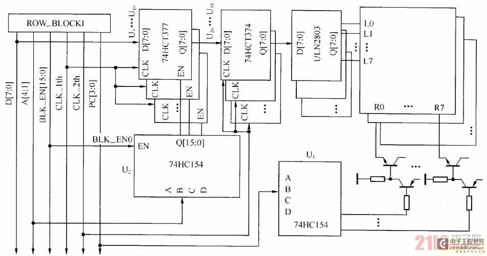
Large-scale LED display system hardware structure and principle
The large-scale LED display system utilizes a line-by-line scanning method and outlines the driving mechanisms to reduce hardware costs. It employs a 1/16 non-interlaced scanning mode, accommodating a total of 16 LED display panels. The schematic diagram of the driver...