


4013 D-type flip-flops
#4013
#D-type flip-flop
#edge-triggered
#clock input
#logic levels
#bistable
#rising-edge
#digital circuits
#CMOS
#sequential logic

Description: The CLOCK input indicates that it is edge-triggered, responding to abrupt changes in voltage rather than gradual changes or steady logic levels. The CLOCK input of the 4013 D-type bistable is specifically rising-edge triggered, meaning it only reacts to a sudden transition from LOW to HIGH. The D-type inputs must be connected to either LOW or HIGH and should not be left open circuit. This requirement also applies to the SET and RESET inputs, which should be connected to 0 V. To prevent loading on the output of the D-type, a transistor switch indicator circuit is utilized. It is advisable to include a decoupling capacitor, either 47 µF or 100 µF, across the power supply in CMOS circuits to mitigate the transfer of voltage spikes along the power supply rails. The output pulses of the bistable are halved compared to the input pulse count. This toggle bistable functions as a divide-by-two counter or a 1-bit binary counter, producing binary outputs that count down from 11 to 00. The constructed circuit acts as a 2-bit binary DOWN counter. D-type bistables can be configured to create a combination lock. By using two 4013 integrated circuits, a 4-digit combination lock can be designed, requiring the correct sequence of key presses to unlock. Pressing a key that does not match the code will RESET all four D-types to a HIGH state. If the correct second digit is pressed, the corresponding D-type will be SET, and this process continues. Incorrect key presses result in a HIGH signal at the RESET inputs of all four bistables. Once all four digits of the code are entered correctly, the lock output will go HIGH and remain in that state until an incorrect key is pressed. The system could also be designed to include an automatic RESET feature after a specified delay.
The 4013 D-type bistable flip-flop is a versatile component in digital electronics, particularly in applications requiring memory storage and state retention. The edge-triggered nature of the CLOCK input allows for precise timing control, making it suitable for synchronous operations. The necessity to connect the D-type inputs to defined logic levels ensures that the device operates reliably without floating inputs, which can lead to unpredictable behavior.
In the context of a combination lock, the use of two 4013 ICs allows for the storage and processing of four distinct states, corresponding to each digit of the code. The design highlights the importance of feedback loops and state management in digital systems, where the SET and RESET functionalities enable the control of the output state based on user input.
Utilizing a transistor switch indicator circuit aids in interfacing with other components without overloading the bistable's output, thus enhancing the overall reliability of the system. The inclusion of a decoupling capacitor is a critical design practice in CMOS circuits, as it stabilizes the power supply and reduces the risk of false triggering due to transient voltage spikes.
The countdown capability of the bistable circuit can be leveraged in various applications beyond combination locks, such as timers, counters, and digital displays. The ability to extend the system with features like automatic RESET demonstrates the flexibility of digital design, allowing for tailored solutions to meet specific operational requirements.Next to the CLOCK input shows that it is edge-triggered, that is, it responds to sudden changes in voltage, but not to slow changes or to steady logic levels. The CLOCK input of the 4013 D-type bistable is rising-edge triggered, meaning that it responds only to a sudden change from LOW to HIGH.
The inputs of the D-type must be connected, either to LOW or to HIGH, and must not be left open circuit. This includes the SET and RESET inputs which are connected to 0 V. To avoid loading the output of the D-type, a transistor switch indicator circuit is used. It is good practice with CMOS circuits to insert a decoupling capacitor, 47 µF or 100 µF, across the power supply. (This helps to prevent the transfer of spikes along the power supply rails. ) As you can see, the number of pulses at the output of the bistable is divided by two compared with the number of pulses at the input.
A toggle bistable is a divide-by-two counter, or 1-bit binary counter. Can you see that the outputs give the binary numbers from 11 to 00 in descending order The circuit you have constructed is a 2-bit binary DOWN counter. D-type bistables can easily be used to make a combination lock. Using two 4013 integrated circuits, you can make a 4-digit combination lock in which the keys representing the code digits must be entered in the correct order.
Pressing the key for any digit which is not part of the code RESETs all four D-types: goes HIGH. If the second digit is the next key presssed, the second D-type will be SET and so on. Pressing any of the unselected keys gives a HIGH at the RESET inputs of all four bistables, and all the Once the four digits of the code have been entered in the correct sequence, the lock ouptut goes HIGH and will remain HIGH until an unselected key is pressed. The system could be extended to provide an automatic RESET after a delay. Which type of subsystem could you use
The 4013 D-type bistable flip-flop is a versatile component in digital electronics, particularly in applications requiring memory storage and state retention. The edge-triggered nature of the CLOCK input allows for precise timing control, making it suitable for synchronous operations. The necessity to connect the D-type inputs to defined logic levels ensures that the device operates reliably without floating inputs, which can lead to unpredictable behavior.
In the context of a combination lock, the use of two 4013 ICs allows for the storage and processing of four distinct states, corresponding to each digit of the code. The design highlights the importance of feedback loops and state management in digital systems, where the SET and RESET functionalities enable the control of the output state based on user input.
Utilizing a transistor switch indicator circuit aids in interfacing with other components without overloading the bistable's output, thus enhancing the overall reliability of the system. The inclusion of a decoupling capacitor is a critical design practice in CMOS circuits, as it stabilizes the power supply and reduces the risk of false triggering due to transient voltage spikes.
The countdown capability of the bistable circuit can be leveraged in various applications beyond combination locks, such as timers, counters, and digital displays. The ability to extend the system with features like automatic RESET demonstrates the flexibility of digital design, allowing for tailored solutions to meet specific operational requirements.Next to the CLOCK input shows that it is edge-triggered, that is, it responds to sudden changes in voltage, but not to slow changes or to steady logic levels. The CLOCK input of the 4013 D-type bistable is rising-edge triggered, meaning that it responds only to a sudden change from LOW to HIGH.
The inputs of the D-type must be connected, either to LOW or to HIGH, and must not be left open circuit. This includes the SET and RESET inputs which are connected to 0 V. To avoid loading the output of the D-type, a transistor switch indicator circuit is used. It is good practice with CMOS circuits to insert a decoupling capacitor, 47 µF or 100 µF, across the power supply. (This helps to prevent the transfer of spikes along the power supply rails. ) As you can see, the number of pulses at the output of the bistable is divided by two compared with the number of pulses at the input.
A toggle bistable is a divide-by-two counter, or 1-bit binary counter. Can you see that the outputs give the binary numbers from 11 to 00 in descending order The circuit you have constructed is a 2-bit binary DOWN counter. D-type bistables can easily be used to make a combination lock. Using two 4013 integrated circuits, you can make a 4-digit combination lock in which the keys representing the code digits must be entered in the correct order.
Pressing the key for any digit which is not part of the code RESETs all four D-types: goes HIGH. If the second digit is the next key presssed, the second D-type will be SET and so on. Pressing any of the unselected keys gives a HIGH at the RESET inputs of all four bistables, and all the Once the four digits of the code have been entered in the correct sequence, the lock ouptut goes HIGH and will remain HIGH until an unselected key is pressed. The system could be extended to provide an automatic RESET after a delay. Which type of subsystem could you use

Magic Wand Conjuring Trick
The operation of the circuit is fairly simple. Three AND logic gates of a 4081 CMOS IC are employed, with gates IC1a to IC1c being configured as a standard cascaded latch circuit. S1 to S3 serve as reset switches. The...

How To Use A Cmos 4017 As A Toggle Switch
This circuit utilizes a CMOS 4017 decade counter, which begins counting from zero and advances by one each time pin 14 is activated. Upon reaching nine, the count resets to zero and starts over. As the count progresses, each output...
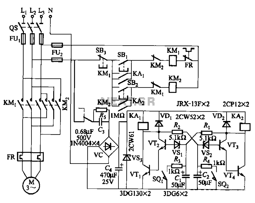
Bistable circuit control motor reversing circuit
The circuit illustrated in Figure 3-72 employs a deformable bistable reversing motor control mechanism that automatically initiates and halts operation during a user-defined time delay. This feature is designed to safeguard the motor from potential impacts during the reversing transition....

Crystal Oscillator with CMOS Inverter
This is an astable multivibrator (oscillator) circuit utilizing a CMOS inverter. The circuit employs the CD4007 or MC14007 components. It operates within a frequency range of...
The astable multivibrator circuit is designed to generate a continuous square wave output without requiring...

Optical-cmos-coupler
Standard CMOS logic operates with supply voltages as low as 3 V and is specified for a maximum current sinking/sourcing capability of 30 pA. To drive the infrared emitting diode (IRED) when utilizing CMOS to control an optocoupler, it is...
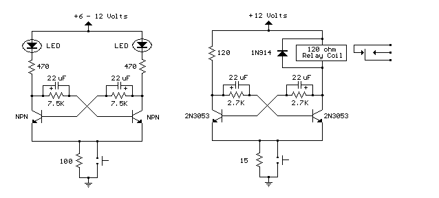
Bistable Flip Flop with relay
Here are two examples of bistable flip flops which can be toggled between states with a single push button. When the button is pressed, the capacitor connected to the base of the conducting transistor will charge to a slightly higher...

CD4013 Push Button CMOS Toggle Flip Flop
The circuit utilizes a CMOS dual D flip-flop (CD4013) to toggle a relay or other load using a momentary push button. Multiple push buttons can be connected in parallel to control the relay from various locations. A high signal from...

Dualxed cmos flasher
Inverters IC1-a and IC1-b form a multivibrator, while IC1-c acts as a buffer. Inverter IC1-d is configured such that its output is the inverse of IC1-c; when pin 6 is high, pin 8 is low, and vice versa. As pins...

TV LINE DECODER I
This circuit generates outputs on TV lines 24 and 257. It was utilized for a decoder circuit and employs a CMOS counter along with gate logic. Only one pin is designated for the output line indicator.
The circuit described serves a...