


6 static display circuit

Description: The static display circuit is illustrated in Figure 6. The 74LS244 acts as bus drivers, and six figures represent a public bus, each equipped with an LED display latch (like the 74LS273) connected to the code for latching the display data. The data is transmitted from the data bus via the 74LS244 to the input of each latch, with the recanalization specified by the address decoder 74LS138. The 74LS244 bus driver is controlled by the IOW and A9 signals, which must be low simultaneously when the output instruction is executed. This allows the 74LS244 to activate and transmit data on the data bus to the corresponding display latches (74LS273). In the circuit depicted, the display bits are addressed sequentially from 100H, 101H, 102H, 103H, 104H, to 105H.
The static display circuit utilizes the 74LS244 as bus drivers to manage data flow to multiple display units. Each unit consists of an LED display latch, specifically the 74LS273, which is responsible for holding the data that will be visually represented. The connection between the data bus and the latches is facilitated by the 74LS244, which ensures that the data is transmitted accurately when the appropriate control signals are activated.
The address decoder, 74LS138, plays a critical role in this circuit by determining which latch should receive the data from the bus. It decodes the address signals and enables the corresponding latch based on the decoded output. The simultaneous activation of the IOW (Input/Output Write) signal and the A9 address line, both being low, triggers the 74LS244 to become operational. This configuration allows for precise control over which display is updated at any given time.
The sequential addressing of the display bits, ranging from 100H to 105H, indicates that there are six distinct latches in the circuit, each capable of holding its own data. When the control signals are correctly set, the 74LS244 transmits the relevant data from the data bus to the selected latch, allowing the LED display to reflect the intended output. This setup is particularly useful in applications requiring multiple visual outputs, such as scoreboards or status indicators, where real-time data representation is crucial.6 shows the static display circuit. Figure, 74LS244 as bus drivers, six figures show a public bus, each with an LED display martyrdom latch (such as 74LS273) connected to the code for latching display data to be displayed. Data is displayed on behalf of code from the data bus via 74LS244 to the input of each latch, recanalization specified by the address decoder 7,415,138± latch latches. 74LS244 bus driver by the IOW and A9 control, when the output instruction is executed so that Lai) W and Ag at the same time is low, 74LS244 to play on, transmitting data on the data bus corresponding to each display latches (74LS273) on.
In the circuit shown in the figure, from left to right each display bit address followed 100H, 101H, 10ZH, 103H, 104H, 105H.
The static display circuit utilizes the 74LS244 as bus drivers to manage data flow to multiple display units. Each unit consists of an LED display latch, specifically the 74LS273, which is responsible for holding the data that will be visually represented. The connection between the data bus and the latches is facilitated by the 74LS244, which ensures that the data is transmitted accurately when the appropriate control signals are activated.
The address decoder, 74LS138, plays a critical role in this circuit by determining which latch should receive the data from the bus. It decodes the address signals and enables the corresponding latch based on the decoded output. The simultaneous activation of the IOW (Input/Output Write) signal and the A9 address line, both being low, triggers the 74LS244 to become operational. This configuration allows for precise control over which display is updated at any given time.
The sequential addressing of the display bits, ranging from 100H to 105H, indicates that there are six distinct latches in the circuit, each capable of holding its own data. When the control signals are correctly set, the 74LS244 transmits the relevant data from the data bus to the selected latch, allowing the LED display to reflect the intended output. This setup is particularly useful in applications requiring multiple visual outputs, such as scoreboards or status indicators, where real-time data representation is crucial.6 shows the static display circuit. Figure, 74LS244 as bus drivers, six figures show a public bus, each with an LED display martyrdom latch (such as 74LS273) connected to the code for latching display data to be displayed. Data is displayed on behalf of code from the data bus via 74LS244 to the input of each latch, recanalization specified by the address decoder 7,415,138± latch latches. 74LS244 bus driver by the IOW and A9 control, when the output instruction is executed so that Lai) W and Ag at the same time is low, 74LS244 to play on, transmitting data on the data bus corresponding to each display latches (74LS273) on.
In the circuit shown in the figure, from left to right each display bit address followed 100H, 101H, 10ZH, 103H, 104H, 105H.

The LED car voltmeter (3)
The LED car voltmeter comprises a filter circuit, a voltage distribution filter circuit, a voltage amplifier circuit, and an LED display circuit, as illustrated in Figure 7-77. The regulator filter circuit includes a 3-terminal IC (IC1) and a filter capacitor...

LED Hat Display with Pong using an Arduino
Some time ago, a Pong game was developed as an initial microcontroller project using a 5G-7 LED display, but it was not pursued further. Recently, a hard hat was provided as part of a uniform for an engineering competition, prompting...

Keyless Lock
The circuit employs a four-bit latch (U1). The sequential nature of the circuit is established by connecting the set input of the first bit latch to the reset of the second bit latch, and this pattern continues for the subsequent...

LED dot display based Battery charge level indicator circuit diagram
In various situations, it is necessary to indicate the amount of battery charge using methods such as LED dot displays or LED bar displays. This circuit utilizes the LM3914 integrated circuit to serve as a battery charge indicator with an...

Common-cathode-led-display
A Teledyne TSC7135 digital voltmeter (DVM) chip is utilized to control a multiplexed 5-digit display. To facilitate common cathode drive, a CD4513BE CMOS integrated circuit (IC) functions as a segment driver, with selection controlled by pins 17-20 of the DVM...

LED Sound level display circuit by using IC LM3915
This is a simple audio sound level LED display circuit diagram. The circuit is entirely based on a single integrated circuit, the LM3915 from National Semiconductor. The LM3915 is a monolithic integrated circuit that displays the audio sound level using...
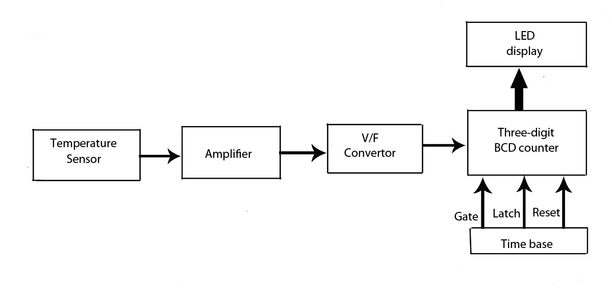
Advanced LED Temperature Indicator
This verified project provides an idea, circuit, and operation of the LED display temperature indicator. It features a digital temperature indicator utilizing a voltage-to-frequency (V/F) converter, along with various electronic projects.
The LED display temperature indicator is designed to provide a...

8x8 dotmatrix scrolling led display
This project involves a scrolling LED display composed of 64 LEDs arranged in a matrix configuration. The anodes of the LEDs are driven by a driver IC, UDN2981, while the cathodes are controlled using the ULN2803. An Atmega8515 microcontroller is...
.gif "Audio Level Meter VU Meter circuit")
Audio Level Meter (VU Meter)
This circuit utilizes a single integrated circuit (IC) along with a minimal number of external components to display audio levels through ten LEDs. The input voltage range is from 12V to 20V, with a recommendation for 12V. The LM3915 is...