


7-Segment (Led) Display Driver Circuit
#7-segment
#LED display
#display driver
#7447 IC
#common anode
#current limiting
#digital circuits
#logic circuits

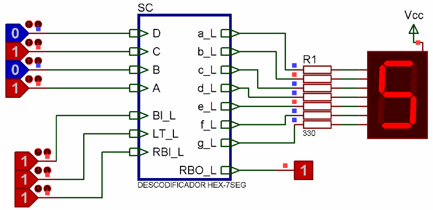
Description: An IC1, such as the 7447, drives a common anode 7-segment LED display. The current-limiting resistor R must restrict the segment current to the rated value at the maximum supply voltage. A sample calculation is provided.
The 7447 integrated circuit is a BCD to 7-segment decoder/driver that converts binary-coded decimal (BCD) inputs into the corresponding output signals that illuminate specific segments of a 7-segment display. In a common anode configuration, the anode of each LED segment is connected to a positive voltage supply, while the cathodes are connected to the output pins of the 7447 IC. When the output of the IC goes low, it allows current to flow through the respective segment, lighting it up.
To ensure proper operation and prevent damage to the LED segments, a current-limiting resistor (R) is necessary. The resistor value can be calculated using Ohm's law and the specifications of the LED display. The maximum forward voltage (Vf) of the segments and the supply voltage (Vs) must be taken into account. The formula to calculate the resistor value is:
R = (Vs - Vf) / If
Where:
- R is the resistance in ohms (Ω),
- Vs is the supply voltage in volts (V),
- Vf is the forward voltage drop across the LED segment in volts (V),
- If is the desired forward current through the LED segment in amperes (A).
For example, if the supply voltage is 5V, the forward voltage drop of the LED is 2V, and the desired forward current is 20mA (0.02A), the calculation would be:
R = (5V - 2V) / 0.02A = 150Ω
This means a 150Ω resistor should be used to limit the current through each segment to the rated value, ensuring optimal performance and longevity of the LED display. Proper selection of the resistor is critical in applications where variations in supply voltage may occur, as it helps maintain consistent brightness and prevents excessive current that could potentially damage the LEDs. An IC1 like a 7447 drives a 7-segment common anode LED display. Current, limiting resistor R should limit the segment current to the rated value at maximum supply voltage. A sample calculation is shown.
The 7447 integrated circuit is a BCD to 7-segment decoder/driver that converts binary-coded decimal (BCD) inputs into the corresponding output signals that illuminate specific segments of a 7-segment display. In a common anode configuration, the anode of each LED segment is connected to a positive voltage supply, while the cathodes are connected to the output pins of the 7447 IC. When the output of the IC goes low, it allows current to flow through the respective segment, lighting it up.
To ensure proper operation and prevent damage to the LED segments, a current-limiting resistor (R) is necessary. The resistor value can be calculated using Ohm's law and the specifications of the LED display. The maximum forward voltage (Vf) of the segments and the supply voltage (Vs) must be taken into account. The formula to calculate the resistor value is:
R = (Vs - Vf) / If
Where:
- R is the resistance in ohms (Ω),
- Vs is the supply voltage in volts (V),
- Vf is the forward voltage drop across the LED segment in volts (V),
- If is the desired forward current through the LED segment in amperes (A).
For example, if the supply voltage is 5V, the forward voltage drop of the LED is 2V, and the desired forward current is 20mA (0.02A), the calculation would be:
R = (5V - 2V) / 0.02A = 150Ω
This means a 150Ω resistor should be used to limit the current through each segment to the rated value, ensuring optimal performance and longevity of the LED display. Proper selection of the resistor is critical in applications where variations in supply voltage may occur, as it helps maintain consistent brightness and prevents excessive current that could potentially damage the LEDs. An IC1 like a 7447 drives a 7-segment common anode LED display. Current, limiting resistor R should limit the segment current to the rated value at maximum supply voltage. A sample calculation is shown.

10 Amp 13 8 Volt Power Supply
The circuit includes a current limiting feature that is more reliable than most commercial units. It employs three pass transistors that require heat sinks. Resistor R9 allows for fine-tuning of the output voltage to precisely 13.8 volts, while the resistor...

Charging capacitor bank with current limiting circuit
A current limiting circuit is designed to select a maximum current through a load, set to a maximum of 480 mA. As the load resistance increases, the series equivalent resistance (SER) of the limiting circuit decreases. When charging a capacitor...

Simple current limiting circuit
When the current is below the specified threshold, the bias current supplied by resistor R1 causes transistor P3 to saturate and conduct. In this state, it is unable to regulate the current effectively. Conversely, when the current reaches or exceeds...

7-Segment & Keypad
Since the output buffer of P1 can sink 20mA (each output pin, but maximum IOL for all outputs was limited at 80mA), thus we can use P1 to drive LED display directly. As shown in the circuit, Two common-anode 7-segment...

Woodstock HP-21 HP-25
The machine utilizes a 12-digit display consisting of 8 LED anodes controlled by an anode driver, and 12 digits managed by a cathode driver, which also scans the keyboard's 7 columns. The bus is simplified to 4 lines: two clock...
.gif "Audio Level Meter VU Meter circuit")
Audio Level Meter (VU Meter)
This circuit utilizes a single integrated circuit (IC) along with a minimal number of external components to display audio levels through ten LEDs. The input voltage range is from 12V to 20V, with a recommendation for 12V. The LM3915 is...
probl
The analysis of simple digital circuits involves determining the circuit's behavior, which is represented by its truth table. To achieve this, the analysis can be organized step by step. For example, consider the circuit from EX1A's Fig. 2b. Note that...

Roulette with LED Display
This circuit is a small digital roulette. It is constituted by oscillator IC1, the counter IC2, the transistors Q1-7 that drive the display common cathode DSP1. The supply basically becomes from a battery 9V, but can become also from one...

Current Limiting for the MAX1864 Auxiliary Regulator
A detailed discussion on implementing current limiting or foldback current limiting for the linear regulator controllers of the MAX1864. This can also be applied to other discrete regulator designs, including the MAX1865, MAX1964, MAX1965, MAX8513, and MAX8514.
To incorporate current limiting...