


8-bit parallel input serial output interface circuit
#parallel input
#serial output
#8-bit
#interface circuit
#shift register
#data conversion
#logic circuit
#digital communication

Description: An 8 parallel input/serial output interface circuit.
An 8 parallel input/serial output interface circuit is designed to convert multiple parallel data inputs into a single serial output stream. This type of circuit is commonly used in digital systems where data needs to be transmitted over a limited number of wires or channels.
The circuit typically consists of eight data input lines, which can be connected to various data sources, such as sensors or microcontrollers. Each input line represents one bit of data. The circuit employs a multiplexer or a shift register to facilitate the conversion of the parallel data into a serial format.
A clock signal is essential for the operation of this interface, as it synchronizes the data transfer process. The clock signal determines when the data on the input lines is sampled and shifted out serially.
In addition, control signals may be included to manage the operation of the circuit, such as enabling or disabling the data transfer or selecting specific input lines for transmission.
The output of the circuit is a single serial data line that can be connected to a microcontroller, communication interface, or any other device that requires serial data input.
This configuration allows for efficient data transmission while minimizing the number of connections required, which is particularly beneficial in applications with space constraints or where wiring complexity must be reduced.8 parallel input/serial output interface circuit as follows:
An 8 parallel input/serial output interface circuit is designed to convert multiple parallel data inputs into a single serial output stream. This type of circuit is commonly used in digital systems where data needs to be transmitted over a limited number of wires or channels.
The circuit typically consists of eight data input lines, which can be connected to various data sources, such as sensors or microcontrollers. Each input line represents one bit of data. The circuit employs a multiplexer or a shift register to facilitate the conversion of the parallel data into a serial format.
A clock signal is essential for the operation of this interface, as it synchronizes the data transfer process. The clock signal determines when the data on the input lines is sampled and shifted out serially.
In addition, control signals may be included to manage the operation of the circuit, such as enabling or disabling the data transfer or selecting specific input lines for transmission.
The output of the circuit is a single serial data line that can be connected to a microcontroller, communication interface, or any other device that requires serial data input.
This configuration allows for efficient data transmission while minimizing the number of connections required, which is particularly beneficial in applications with space constraints or where wiring complexity must be reduced.8 parallel input/serial output interface circuit as follows:

8-bit bus control widely used 12-bit DA converter Universal
The 8 microcomputer data operates with an 8-bit parallel output, while also accommodating serial input for D-A converters. Typically, data must be entered in two groups and processed as a whole. The requirements for data latching involve 16 straight odd...

Lights Out circuit
The design is based on the previous analysis of calculating the game in a circular shift register. While designing, it was realized that small extensions to the design would enable additional gameplay features, such as replay and manual input. The...

Coincidence Detector for Logic Signals
This is a coincidence detector circuit. This circuit is very useful for monitoring complex logic circuits. This circuit has two inputs, A and B. If A and B are...
The coincidence detector circuit is designed to identify when two input signals,...

Shift register sequencer circuit
The mechanics of the Quantized Random Voltage function are intriguing. Instead of having fixed quantization steps for each output of the 4006 shift register, it is proposed to make the voltages adjustable through potentiometers. The Quantized Random Voltage function utilizes...

Shift register on a schematic
The circuit features a shift register chip (74HC595N), which is not available on CircuitLab. There may be a specific representation for a shift register in schematic diagrams. Although assistance with CircuitLab is not provided, schematic illustrations can be referenced on...

Shift register driver
A 16V power supply can be synthesized using IN1692 rectifiers. A shift pulse input saturates the 2N2714, depriving the Darlington combination (2N2714 and 2N2868) of base drive. The negative pulse generated on the 15V line is differentiated to produce a...

OSU8 Microprocessor Project (1994)
OSU8 began as a student project in 1994 to create a simple but functional 8-bit microprocessor, starting with a definition of the architecture to implementation in a Xilinx FPGA chip, and full-custom CMOS implementation. Over a period of about six...

Shift register
The shift pulse amplitude is less than 15 volts. If a stage is off, the shift pulse will not be coupled to the next stage. If it is on, the diode will conduct triggering the next stage. Just prior to...
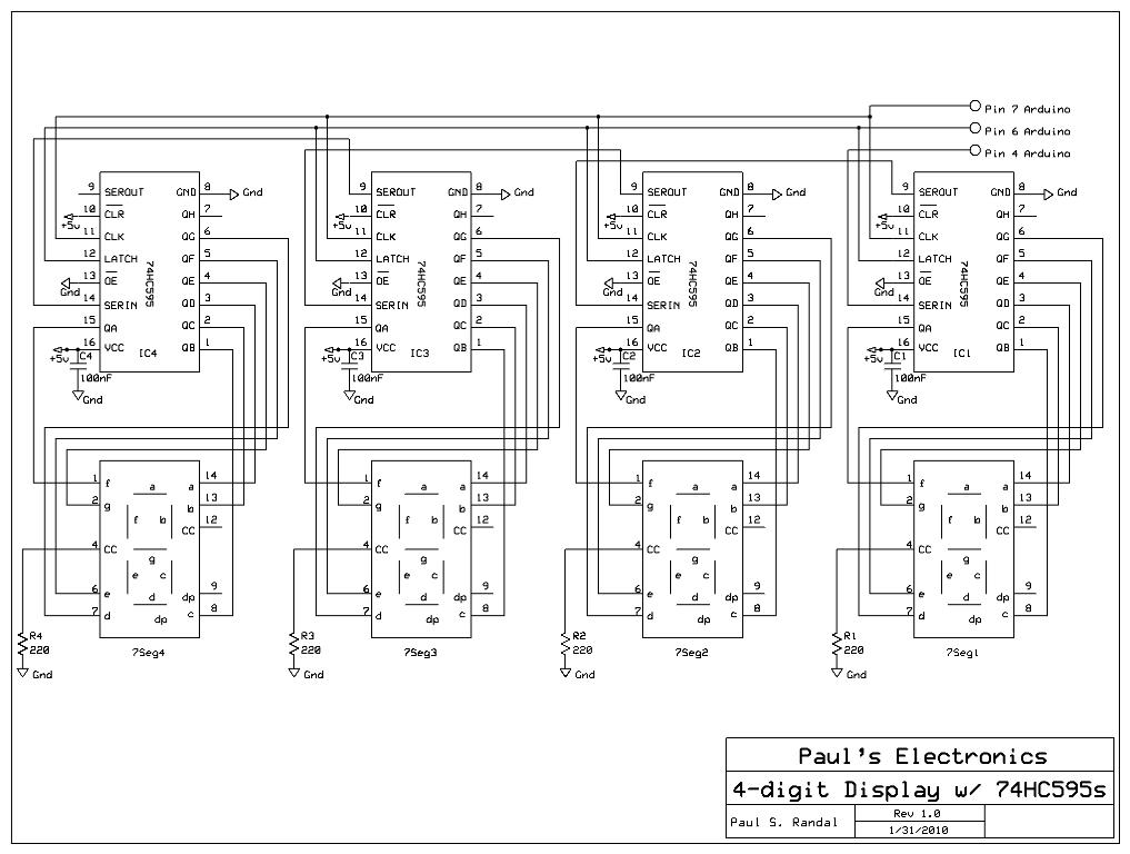
cascading shift registers to drive 7-segment displays with PC input
Four 595 shift registers are used together to drive 7-segment displays, with additional code implemented to accept input from a PC. Unlike the previous design that utilized 10-LED bar graphs, the current configuration employs 7-segment displays, which present a greater...