


A. A. van Zoelen`s "Z-bridge"
#74F139
#74S139
#motor control
#current limit
#digital logic
#peak current
#output
#circuit design
#misbehavior

Description: You can drop all off the transistors and resistors if your motors don’t drain too much current. You only need a 74F139 or 74S139 NOT the LS version. The chip can provide peak currents up to 100mA for a short time (<1 second) and to one output at a time. This is for normal connections. I don’t know how far you can go with this misbehavior. It’s nothing special, but you get the idea how it is done.
The circuit described involves the use of a 74F139 or 74S139 dual 2-to-4 line decoder/demultiplexer, which is suitable for applications where limited current output is required, such as controlling small motors. The choice of the 74F139 or 74S139 over the LS version is crucial due to their higher output current capabilities. The 74F139 can drive up to 100mA per output for brief periods, making it suitable for applications where short bursts of power are needed, such as starting small motors.
In typical configurations, the outputs of the 74F139 or 74S139 can be used to activate different motors or other loads. When designing the circuit, it is essential to ensure that the total current drawn by the motors does not exceed the specified limits of the chip. The outputs should be connected directly to the motors, with adequate consideration for the inductive kickback that motors can produce. This can be mitigated by incorporating flyback diodes across the motor terminals to protect the IC from voltage spikes.
For applications where the motors require continuous operation, additional components such as transistors may be necessary to handle the higher current demands. However, if the motors are low-power and do not exceed the current rating of the 74F139 or 74S139, the circuit can be simplified by eliminating these components.
In summary, the circuit leverages the capabilities of the 74F139 or 74S139 for controlling motors with low current demands, allowing for a straightforward design while ensuring protection against potential damage from inductive loads.You can drop all off the transistors and resistors if your motors don`t drain too much current. You only need a 74F139 or 74S139 NOT the LS version. The chip can provide peak currents up to 100mA for a short time (<1 second) and to one output at a time. This is for normal connections. I don`t know how far you can go with this misbehavior. It`s nothing special, but you get the idea how it is done.
The circuit described involves the use of a 74F139 or 74S139 dual 2-to-4 line decoder/demultiplexer, which is suitable for applications where limited current output is required, such as controlling small motors. The choice of the 74F139 or 74S139 over the LS version is crucial due to their higher output current capabilities. The 74F139 can drive up to 100mA per output for brief periods, making it suitable for applications where short bursts of power are needed, such as starting small motors.
In typical configurations, the outputs of the 74F139 or 74S139 can be used to activate different motors or other loads. When designing the circuit, it is essential to ensure that the total current drawn by the motors does not exceed the specified limits of the chip. The outputs should be connected directly to the motors, with adequate consideration for the inductive kickback that motors can produce. This can be mitigated by incorporating flyback diodes across the motor terminals to protect the IC from voltage spikes.
For applications where the motors require continuous operation, additional components such as transistors may be necessary to handle the higher current demands. However, if the motors are low-power and do not exceed the current rating of the 74F139 or 74S139, the circuit can be simplified by eliminating these components.
In summary, the circuit leverages the capabilities of the 74F139 or 74S139 for controlling motors with low current demands, allowing for a straightforward design while ensuring protection against potential damage from inductive loads.You can drop all off the transistors and resistors if your motors don`t drain too much current. You only need a 74F139 or 74S139 NOT the LS version. The chip can provide peak currents up to 100mA for a short time (<1 second) and to one output at a time. This is for normal connections. I don`t know how far you can go with this misbehavior. It`s nothing special, but you get the idea how it is done.

motor timer
The primary concept is to rotate the motor slightly every 15 seconds. A monofilament line conveys the motion to the ornament, which is wound by the motor and gradually unwinds as the ornament turns. The charging circuit includes a 1...
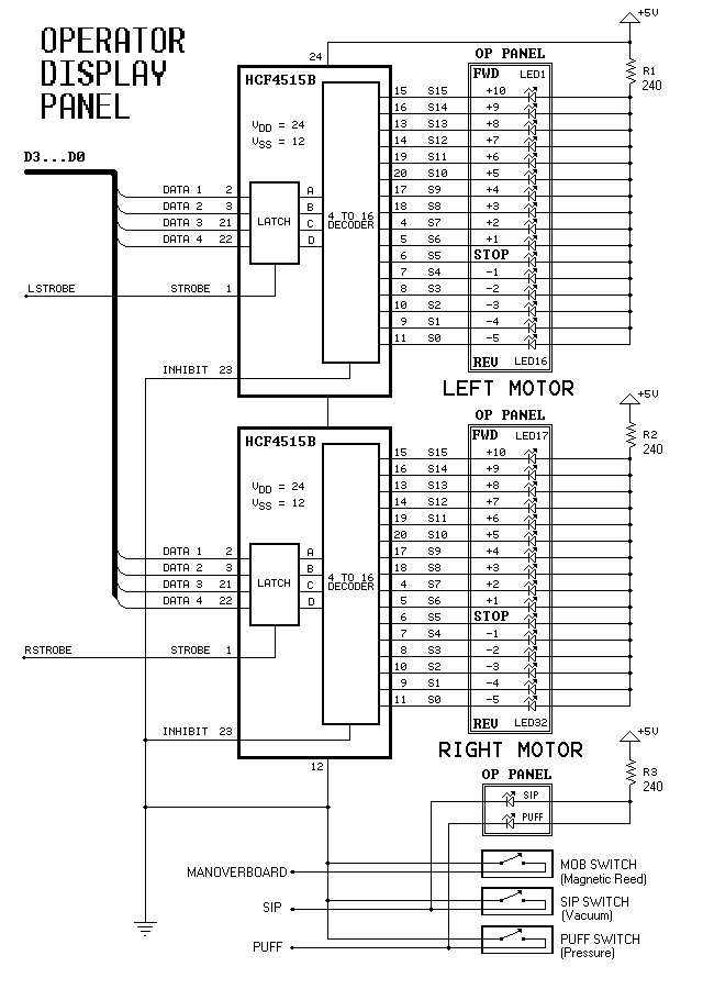
Dual-Motor SIP&PUFF Controlled Kayak System
The YouTube video below demonstrates the quick and easy setup of the system at the launch site.
The provided description indicates a focus on the efficiency of system installation at a launch site, as showcased in a YouTube video. In an...

2 -Y- connection automatic three-speed motor acceleration control circuit
Figure 3-118 illustrates an automatic acceleration control circuit. This circuit employs a male contactor time relay, enabling the motor to start automatically at a low speed before transitioning to high-speed operation.
The automatic acceleration control circuit depicted in Figure 3-118 is...

Adjustable Current Limit For Dual Power Supply
This current-limiting circuit, illustrated as part of a small bench power supply, can be utilized with any dual-rail current source. The section of the circuit to the left limits the current at the input to the dual voltage regulator (IC4...
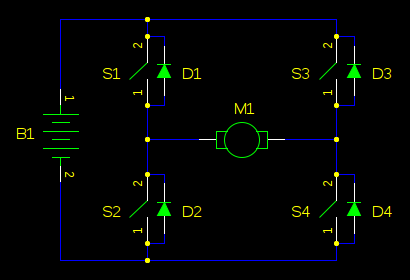
boost Why should I worry about a motor causing my supply voltage to shoot up when the back-EMF cant exceed the supply voltage
In motor control circuits, precautions must be taken to prevent the motor from feeding back into the power supply, which can cause the supply voltage to rise and potentially damage components. However, unless an external force is accelerating the motor,...

Universal motor control
When the time delay expires, SCR1 conducts and removes the gate signal from SCR2, which stops the motor. Both the time delay and motor speed are adjustable by potentiometers R2 and R3. If heavier motor loads are anticipated, use the...
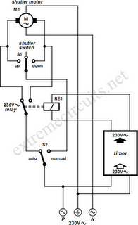
To Automate Rolling Shutter Motor
To automate the opening and closing of a rolling shutter using a time-controlled switch, additional wiring will be necessary.
To implement an automated system for a rolling shutter, a time-controlled switch can be utilized to manage the operation of the shutter....

Series-Wound Direction And Speed Motor Control
This is a motor controller circuit that controls the speed and direction of series-wound motors. This circuit employs silicon controlled rectifiers (SCR).
The motor controller circuit is designed to manage both the speed and direction of series-wound motors, which are commonly...

Current Limit Circuit for Voltage Regulator
This is a cost-effective circuit that incorporates precise current limiting functionality into a voltage regulator.
The circuit described is designed to enhance the performance of a voltage regulator by integrating a current limiting feature. This is particularly beneficial in applications where...