


Asynchronous counter circuit and the signal waveform
#asynchronous counter
#counter
#digital circuit
#signal waveform
#clock synchronization
#logic design
#flip-flop
#sequential logic

Description: An asynchronous counter is illustrated in this circuit. It operates without a clock synchronization signal, making it suitable for use in a random counter or as an independent unit circuit.
An asynchronous counter, also known as a ripple counter, is a digital circuit that counts in binary without relying on a common clock signal to trigger all flip-flops simultaneously. Instead, each flip-flop in the counter is triggered by the output of the preceding flip-flop, resulting in a ripple effect. This characteristic allows for the design of counters that can operate independently or in applications where precise timing is not critical.
The basic configuration of an asynchronous counter typically involves a series of flip-flops (commonly T or JK flip-flops) connected in a cascading manner. The first flip-flop is usually triggered by an external input signal, while each subsequent flip-flop is triggered by the output of the previous one. As a result, the output state of the counter changes in response to the input signal, with a delay introduced by the propagation time through each flip-flop.
The primary advantage of an asynchronous counter is its simplicity and ease of implementation, as it does not require a centralized clock signal. This feature makes it suitable for applications where the speed of operation is less critical, and cost-effective solutions are desired. However, the main drawback is that the propagation delay can lead to inaccuracies in counting at higher frequencies, as the ripple effect can cause the output to change in a non-uniform manner.
In practical applications, asynchronous counters are often used in digital clocks, frequency dividers, and event counters, where the counting does not need to be synchronized with a clock signal. The design of such counters can be tailored to meet specific requirements, such as counting in binary, BCD (Binary-Coded Decimal), or other number systems, depending on the configuration of the flip-flops and the logic circuitry employed. Asynchronous counter shown, this circuit no clock synchronization signal can be used in a random counter or independent unit circuit.
An asynchronous counter, also known as a ripple counter, is a digital circuit that counts in binary without relying on a common clock signal to trigger all flip-flops simultaneously. Instead, each flip-flop in the counter is triggered by the output of the preceding flip-flop, resulting in a ripple effect. This characteristic allows for the design of counters that can operate independently or in applications where precise timing is not critical.
The basic configuration of an asynchronous counter typically involves a series of flip-flops (commonly T or JK flip-flops) connected in a cascading manner. The first flip-flop is usually triggered by an external input signal, while each subsequent flip-flop is triggered by the output of the previous one. As a result, the output state of the counter changes in response to the input signal, with a delay introduced by the propagation time through each flip-flop.
The primary advantage of an asynchronous counter is its simplicity and ease of implementation, as it does not require a centralized clock signal. This feature makes it suitable for applications where the speed of operation is less critical, and cost-effective solutions are desired. However, the main drawback is that the propagation delay can lead to inaccuracies in counting at higher frequencies, as the ripple effect can cause the output to change in a non-uniform manner.
In practical applications, asynchronous counters are often used in digital clocks, frequency dividers, and event counters, where the counting does not need to be synchronized with a clock signal. The design of such counters can be tailored to meet specific requirements, such as counting in binary, BCD (Binary-Coded Decimal), or other number systems, depending on the configuration of the flip-flops and the logic circuitry employed. Asynchronous counter shown, this circuit no clock synchronization signal can be used in a random counter or independent unit circuit.

Synchronous RS flip-flop circuit structure and symbols
The asynchronous RS flip-flop mentioned earlier is not synchronized with the system clock signal. In contrast, the synchronous RS flip-flop incorporates synchronization, allowing it to operate in conjunction with the clock signal. Figure (a) illustrates the circuit configuration of the...

digital counter circuit
The Digital Counter Circuit is an electronic project that converts digital numbers (0-9) to binary (0-1). For those interested in understanding binary code, a PowerPoint presentation on the topic is available. Below are the parts list, schematic, and additional information...

RING COUNTER WITH VISUAL READOUT
The circuit utilizes only six components per stage. By integrating counter and indicator functions, it achieves low battery consumption. Once the reset button is released, a 0.22 µF capacitor ensures that the first stage activates. Current is drawn by the...

Opto-Coupled RS Flip-Flop
An RS flip-flop, also known as a reset-set flip-flop, is a type of stable multivibrator that has two inputs: reset and set. The output can exist in one of two stable states.
The RS flip-flop is a fundamental building block in...

LOGIC DESIGNER
The logic designer is filled with features. It would not be possible to list all the possible combinations of the unit as the various building blocks on the board can be interconnected to obtain a wide variety of counting and...

Divide-By-Odd-Number Counter
This circuit symmetrically divides an input by virtually any odd number. The circuit contains n + 1 clocks to achieve the desired divisor. By selecting the proper n, which is the decoded output of the 74LS161 counter, divisors from 3...
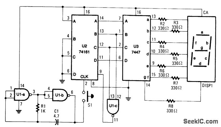
ELECTRONIC DICE
When S1 is pressed, counter U2 is activated by oscillator U1A/U1B, and the count (ranging from 0 to 6) is displayed on DISP1. The resistor R1 and capacitor C1 define the count rate, which must be sufficiently rapid to produce...

8-Digit up-down counter
This circuit illustrates the method of cascading counters while maintaining the appropriate leading zero blanking. A NAND gate is employed to determine if a digit is active, as indicated by the activation of either segment a or b on any...

MULTIDIGIT DEMONSTRATION COUNTER
A simple interconnection of the RS7490 decade counter, RS7447 decoder, and a 7-segment digital display for each desired digit creates an ideal counter for classroom demonstrations and science fair exhibits. With the addition of two extra stages, the display can...