


Audible Logic Probe with LM339

Description: When testing circuits with a logic probe, it is sometimes difficult to watch the LEDs on the probe to determine the logic state. With this probe, the logic states are audible. This probe is designed for TTL circuits only but could be modified for CMOS. The way it works is as follows. The 5-volt power source will be the circuit under test. Clip the ground input of the probe to the ground of the circuit being tested. The other input lead is used to probe the different chips of the circuit being tested. Any input greater than 2 volts will be high and output a high tone through the speaker. Any input less than 0.8 volts will be low and produce a low tone through the speaker.
The audible logic probe operates based on the voltage levels present in TTL (Transistor-Transistor Logic) circuits. The primary components of the probe include a voltage comparator, a tone generator, and an audio output device, typically a small speaker or piezo buzzer.
The voltage comparator is configured to compare the input voltage from the circuit under test against two reference voltages: 2 volts and 0.8 volts. When the probe tip is connected to a point in the circuit, the input voltage is fed into the comparator. If the voltage exceeds 2 volts, the comparator outputs a signal that activates the tone generator to produce a high-frequency tone, indicating a logic high state. Conversely, if the voltage falls below 0.8 volts, the comparator triggers the tone generator to produce a low-frequency tone, indicating a logic low state.
For proper operation, the probe is powered by a 5-volt source, which is typically the same voltage used in TTL circuits. The ground clip must be connected to the circuit's ground to ensure accurate voltage readings. The probe's design can be adapted for CMOS (Complementary Metal-Oxide-Semiconductor) circuits by adjusting the reference voltage levels to accommodate the different voltage ranges used in those applications.
In summary, the audible logic probe is a valuable tool for quickly assessing the logic state of various points in a TTL circuit, providing immediate auditory feedback that can enhance the efficiency of circuit testing and troubleshooting.When testing circuits with a logic probe, it is sometimes difficult to watch the LEDS on the probe to determine the logic state. With this probe the logic states are audible. This probe is designed for TTL circuits only but could be modified for CMOS. The way it works is as follows. The 5 volt power source will be the circuit under test. Clip the ground input of the probe to the ground of the circuit being tested. The other input lead is used to probe the different chips of the circuit being tested. Any input greater then 2 volts will be high and output a high tone through the speaker. Any input less then .8 volts will be low and produce a low tone through the speaker.
The audible logic probe operates based on the voltage levels present in TTL (Transistor-Transistor Logic) circuits. The primary components of the probe include a voltage comparator, a tone generator, and an audio output device, typically a small speaker or piezo buzzer.
The voltage comparator is configured to compare the input voltage from the circuit under test against two reference voltages: 2 volts and 0.8 volts. When the probe tip is connected to a point in the circuit, the input voltage is fed into the comparator. If the voltage exceeds 2 volts, the comparator outputs a signal that activates the tone generator to produce a high-frequency tone, indicating a logic high state. Conversely, if the voltage falls below 0.8 volts, the comparator triggers the tone generator to produce a low-frequency tone, indicating a logic low state.
For proper operation, the probe is powered by a 5-volt source, which is typically the same voltage used in TTL circuits. The ground clip must be connected to the circuit's ground to ensure accurate voltage readings. The probe's design can be adapted for CMOS (Complementary Metal-Oxide-Semiconductor) circuits by adjusting the reference voltage levels to accommodate the different voltage ranges used in those applications.
In summary, the audible logic probe is a valuable tool for quickly assessing the logic state of various points in a TTL circuit, providing immediate auditory feedback that can enhance the efficiency of circuit testing and troubleshooting.When testing circuits with a logic probe, it is sometimes difficult to watch the LEDS on the probe to determine the logic state. With this probe the logic states are audible. This probe is designed for TTL circuits only but could be modified for CMOS. The way it works is as follows. The 5 volt power source will be the circuit under test. Clip the ground input of the probe to the ground of the circuit being tested. The other input lead is used to probe the different chips of the circuit being tested. Any input greater then 2 volts will be high and output a high tone through the speaker. Any input less then .8 volts will be low and produce a low tone through the speaker.
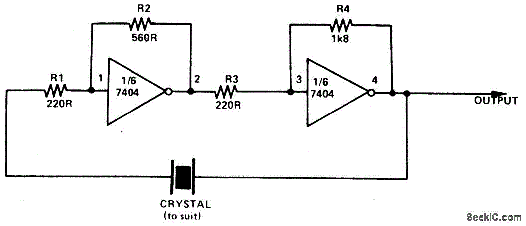
SIMPLE TTL CRYSTAL OSCILLATOR
This simple and inexpensive crystal oscillator consists of one-third of a 7404 hex inverter, four resistors, and a crystal. The inverters are biased into their linear regions by resistors R1 to R4, while the crystal provides the necessary feedback. Oscillation...

Motor Control Circuit of LM339
The motor control circuit depicted in the image utilizes the LM339 comparator among other components. When the input control signal is high (PWL), comparators A and A3 activate the power amplifier circuit, which consists of A4, VT5, and VT6, thereby...
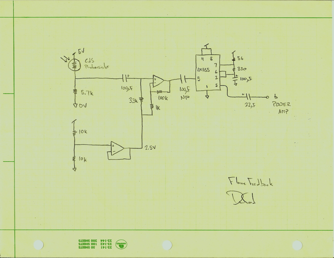
Flame Feedback
Flame Feedback is a sound sculpture constructed from a speaker driver, a candle, and electronic components. The speaker is activated with a low-frequency tone, which moves air and causes the candle to flicker. An optical sensor detects the flicker of...
Motor Control Circuit of LM339
The motor control circuit depicted in the image utilizes the LM339 comparator among other components. When the input control signal is high (PWL), comparators A and A3 activate the power amplifier circuit, which consists of A4, VT5, and VT6, thereby...

Low Voltage High Current Time Delay Circuit
In this circuit, an LM339 quad voltage comparator is utilized to generate a time delay and control a high current output at low voltage. Approximately 5 amps of current can be sourced using a pair of fresh alkaline D batteries....

Stimulated simple motor speed control circuit
The LM339 comparator IC (Integrated Circuit) is utilized to enhance the functionality of electric circuits. A potentiometer (B) is incorporated to adjust the desired setpoint, while a feedback signal is generated by resistor (R). A significant pressure point is established,...

Speaker to microphone converter circuit
This circuit provides a straightforward method for converting a loudspeaker into a microphone. When sound waves impact the diaphragm of the speaker, fluctuations occur in the coil, generating a small induced voltage that is typically low in magnitude and not...

Logic Probe
This logic probe uses a single CMOS IC and shows three logic conditions, High, Low and Pulsing. In addition if the probe input is neither hi or low (the high impedance state of tri-output logic ic`s) then no LED`s will...

Logic Probe Plans
This document presents a set of plans for constructing an affordable, high-performance digital logic probe that can be assembled within a few hours. The design utilizes a plastic ballpoint pen as the chassis, providing a unique and stylish appearance. A...