


Bistable circuit at the operating frequency of 100kHz or less

Description: Bistable circuit operating at a frequency of 100 kHz or less.
A bistable circuit, also known as a flip-flop, is a type of electronic circuit that has two stable states and can be used to store binary information. This circuit can maintain its state indefinitely until an external trigger causes it to change states. The operating frequency of 100 kHz or less indicates that the circuit is suitable for applications where high-speed operation is not required, making it ideal for various control and memory applications.
Typically, a bistable circuit can be implemented using different configurations, such as the SR (Set-Reset) flip-flop, D (Data) flip-flop, or JK flip-flop. Each of these configurations has specific input and output characteristics that can be leveraged based on the application requirements.
In a basic SR flip-flop, two cross-coupled NOR or NAND gates are used. The inputs are labeled 'Set' and 'Reset.' When the Set input is activated, the output will transition to a high state, and when the Reset input is activated, the output will transition to a low state. The circuit remains in the last state until either input is triggered again.
For a D flip-flop, a single data input is used along with a clock signal. The output follows the data input when the clock signal transitions, thus providing a simple way to store a single bit of information. The D flip-flop is particularly useful in synchronous systems where data needs to be captured at specific intervals.
The JK flip-flop extends the functionality of the SR flip-flop by allowing both inputs to be active simultaneously. This characteristic enables toggling of the output state when both inputs are high, making it suitable for counters and more complex state machines.
In designing a bistable circuit to operate at frequencies of 100 kHz or less, considerations should include the choice of components, such as the type of logic gates used, the power supply voltage, and the load capacitance. The timing characteristics, including propagation delay and setup/hold times, must also be analyzed to ensure reliable operation within the specified frequency range.
Overall, a bistable circuit is a fundamental building block in digital electronics, enabling the implementation of memory elements, state machines, and various control logic applications. Bistable circuit at the operating frequency of 100kHz or less
A bistable circuit, also known as a flip-flop, is a type of electronic circuit that has two stable states and can be used to store binary information. This circuit can maintain its state indefinitely until an external trigger causes it to change states. The operating frequency of 100 kHz or less indicates that the circuit is suitable for applications where high-speed operation is not required, making it ideal for various control and memory applications.
Typically, a bistable circuit can be implemented using different configurations, such as the SR (Set-Reset) flip-flop, D (Data) flip-flop, or JK flip-flop. Each of these configurations has specific input and output characteristics that can be leveraged based on the application requirements.
In a basic SR flip-flop, two cross-coupled NOR or NAND gates are used. The inputs are labeled 'Set' and 'Reset.' When the Set input is activated, the output will transition to a high state, and when the Reset input is activated, the output will transition to a low state. The circuit remains in the last state until either input is triggered again.
For a D flip-flop, a single data input is used along with a clock signal. The output follows the data input when the clock signal transitions, thus providing a simple way to store a single bit of information. The D flip-flop is particularly useful in synchronous systems where data needs to be captured at specific intervals.
The JK flip-flop extends the functionality of the SR flip-flop by allowing both inputs to be active simultaneously. This characteristic enables toggling of the output state when both inputs are high, making it suitable for counters and more complex state machines.
In designing a bistable circuit to operate at frequencies of 100 kHz or less, considerations should include the choice of components, such as the type of logic gates used, the power supply voltage, and the load capacitance. The timing characteristics, including propagation delay and setup/hold times, must also be analyzed to ensure reliable operation within the specified frequency range.
Overall, a bistable circuit is a fundamental building block in digital electronics, enabling the implementation of memory elements, state machines, and various control logic applications. Bistable circuit at the operating frequency of 100kHz or less
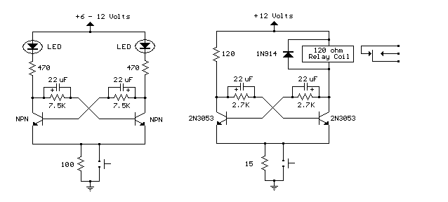
Bistable Flip Flop with relay
Here are two examples of bistable flip flops which can be toggled between states with a single push button. When the button is pressed, the capacitor connected to the base of the conducting transistor will charge to a slightly higher...

Homemade Digital CALL-ID English Version
The reason for this project was to facilitate a quick installation for a local friend 10 km away, enabling the start of real-life testing to identify and resolve bugs and problems before releasing it to other users. The software is...

Simple Digital Logic Probe Circuit
The design of the digital logic probe centers around a pair of complementary bipolar transistors, which, in this application, are used as electronic switches.
The digital logic probe is a diagnostic tool utilized for testing and analyzing digital circuits. The core...

Spare-flip-flop-inverter
The circuit utilizes one-half of a dual D flip-flop as an inverter. When the input signal decreases, the flip-flop resets, causing its Q output to increase. Conversely, when the input signal increases, the reset line is released, and the Q...

Digital pulse width measurement circuit diagram CD4518 and CD4069 the
A digital pulse width measurement circuit is presented. It operates with a 100 kHz reference frequency to count the pulse width of the input signal. The count value represents the measured pulse width displayed on four seven-segment LED displays. The...

The 6090 Digital Decoder
This is an image Schematic. No Description available.
The provided input indicates that there is a schematic image, but no additional descriptive information is available regarding its components, functionality, or application. In the context of electronic schematics, such images typically...

Practical flip-flop circuit
A flip-flop circuit with a memory function for pulse signals. It features two stable states: one where transistor VTi is off and VTZ is conducting, and another where VTi is conducting and VT2 is off. An external signal is sufficient...

Bistable circuit at the operating frequency of 10kHz or less
Bistable circuit operating at a frequency of 10 kHz or lower.
A bistable circuit, also known as a flip-flop, is a fundamental building block in digital electronics. It has two stable states and can store one bit of data. The circuit...

Frequency warning alarm
A low-frequency oscillator (Q1) modulates a high-frequency oscillator (Q2) along with its associated timing capacitor. The output frequency varies continuously.
The circuit comprises two primary components: the low-frequency oscillator (Q1) and the high-frequency oscillator (Q2). The low-frequency oscillator is responsible for...