


Decimal to BCD Convertor Keypad
#decimal to BCD
#keypad
#BCD converter
#HEX to BCD
#digital conversion
#logic circuits
#binary coded decimal
#output encoding
#keypad interface

Description: When any particular key is pressed, its value will appear in BCD form at the outputs (A, B, C & D). It will remain there until another key is pressed. The 12 keys produce outputs up to "1011". Extended to 16 keys, the circuit will give the full HEX to BCD conversion. The above circuit produces an output ONLY while the input switch is depressed. To make a convertor with a latched output, the following modifications are made. Each CMOS AND gate has its free input tied to Vcc, and by the action of R1 through
The described circuit functions as a binary-coded decimal (BCD) converter, which translates the pressed key value into a BCD output format. The outputs A, B, C, and D represent the four bits of the BCD code, allowing for the representation of decimal digits 0 through 9. When one of the 12 keys is pressed, the corresponding BCD value is generated and held at the outputs until a different key is pressed, which then updates the displayed value.
For applications requiring an extended range, the circuit can accommodate up to 16 keys, yielding a full hexadecimal to BCD conversion. This enhancement enables the representation of values from 0 to 15 in hexadecimal format, which corresponds to 0000 to 1111 in binary.
The initial design outputs a signal only while the key is actively pressed, which may not be suitable for all applications. To create a latching output that maintains the last pressed key's value even after the key is released, modifications are necessary. Each CMOS AND gate in the circuit is configured with its free input connected to the positive supply voltage (Vcc). This configuration allows the circuit to maintain the last output state by leveraging the characteristics of the CMOS technology, which consumes minimal power and provides high noise immunity.
Additionally, a resistor (R1) is introduced in the circuit to help manage the timing and stability of the latching mechanism. This resistor can influence the charging and discharging rates of any capacitive elements present in the circuit, thereby affecting the response time and the overall performance of the latch. The precise values of R1 and any other components will depend on the specific requirements of the application, such as the desired response time and the load characteristics of the output.
Overall, this circuit design provides a robust solution for converting key presses into a stable BCD output, with the flexibility to extend its functionality through the incorporation of additional keys and latching mechanisms.When any particular key is pressed, its value will appear in BCD form at the outputs (A, B, C & D). It will remain there until another key is pressed. The 12 keys produce outputs up to "1011". Extended to 16 keys, the circuit will give the full HEX to BCD conversion. The above circuit produces an output ONLY while the input switch is depressed. To make a convertor with a latched output, the following modifications are made. Each CMOS `AND` gate has its free input tied to Vcc, and by the action of R1 through
The described circuit functions as a binary-coded decimal (BCD) converter, which translates the pressed key value into a BCD output format. The outputs A, B, C, and D represent the four bits of the BCD code, allowing for the representation of decimal digits 0 through 9. When one of the 12 keys is pressed, the corresponding BCD value is generated and held at the outputs until a different key is pressed, which then updates the displayed value.
For applications requiring an extended range, the circuit can accommodate up to 16 keys, yielding a full hexadecimal to BCD conversion. This enhancement enables the representation of values from 0 to 15 in hexadecimal format, which corresponds to 0000 to 1111 in binary.
The initial design outputs a signal only while the key is actively pressed, which may not be suitable for all applications. To create a latching output that maintains the last pressed key's value even after the key is released, modifications are necessary. Each CMOS AND gate in the circuit is configured with its free input connected to the positive supply voltage (Vcc). This configuration allows the circuit to maintain the last output state by leveraging the characteristics of the CMOS technology, which consumes minimal power and provides high noise immunity.
Additionally, a resistor (R1) is introduced in the circuit to help manage the timing and stability of the latching mechanism. This resistor can influence the charging and discharging rates of any capacitive elements present in the circuit, thereby affecting the response time and the overall performance of the latch. The precise values of R1 and any other components will depend on the specific requirements of the application, such as the desired response time and the load characteristics of the output.
Overall, this circuit design provides a robust solution for converting key presses into a stable BCD output, with the flexibility to extend its functionality through the incorporation of additional keys and latching mechanisms.When any particular key is pressed, its value will appear in BCD form at the outputs (A, B, C & D). It will remain there until another key is pressed. The 12 keys produce outputs up to "1011". Extended to 16 keys, the circuit will give the full HEX to BCD conversion. The above circuit produces an output ONLY while the input switch is depressed. To make a convertor with a latched output, the following modifications are made. Each CMOS `AND` gate has its free input tied to Vcc, and by the action of R1 through

keypad controlled switch
This is a simplified version of the 4-Digit Keypad Controlled Switch. The design has been modified to reduce circuit complexity and the number of components required. Consequently, the code is somewhat less secure, but it should be sufficient for many...

5 digit alarm control keypad
This keypad is designed for use with the Modular Burglar Alarm system, although it can be applied in various other contexts. Inputting the first four digits of a selected five-digit code will activate the relay, while entering the complete five-digit...

How To Build A Keypad-Operated Door-Lock Release
This circuit is designed to operate an electrical door-release mechanism, but it can also be used for other applications. Users can enter a four-digit code of their choice, which will energize a relay for a duration determined by the components...

How To Build A Simple Keypad Switch With A Tamper Alarm
This circuit is designed for use with a Universal Keypad Operated Switch. A few genuine mistakes made during code entry will not activate the device. However, repeated attempts to input the correct code through trial and error will cause the...

MultiKey - One Wire Keypad
This project can be utilized for various purposes, with one of the most common applications being the interfacing of a keypad for electronic projects. While several pre-made keypads are available on the market, they typically operate with matrix connections, requiring...

Keypad and LCD Display Module for Data Entry
Control your instrument with a 4x20 LCD display and a 4x5 keypad designed for front panel feedback and control.
The circuit involves an interface that utilizes a 4x20 LCD display and a 4x5 keypad, providing an effective means of user interaction...

Enhanced 4 Digit Alarm Keypad
The Keypad must be the kind with a common terminal and a separate connection for each key. On a 12-key pad, look for 13 terminals. The matrix type with 7 terminals will NOT do. The Alarm is set by pressing...
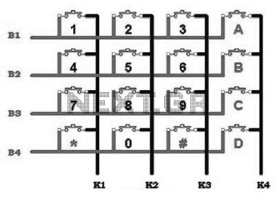
control keypad interfacing
This includes an interface that is simple enough for mastery, as the keypad supports input facilities commonly used in Man-Machine Interface (MMI) applications. For example, various types of keypads can be found in the market. This discussion will focus on...

MEM 800
This website provides schematics and instructions for constructing a keypad circuit that can be interfaced with a PC using an 8255 PC interface board. The keypad is directly connected to a client computer, which transmits information from the keypad over...