


Decoding IC 74LS47 7 segment LED
#74LS47
#7-segment display
#decoder
#common anode
#digital circuit
#LED
#IC
#binary decoder
#display driver
#TTL

Description: The 7447 is a widely used electronic integrated circuit (IC) with various designations depending on the manufacturer, such as 74HC47, 74HCT47, and 74LS47. This IC serves as a dedicated decoder for common anode LED 7-segment displays. It is particularly useful in applications requiring the display of numerical values on a 7-segment LED without the need for a microprocessor, thereby saving board space.
The circuit operates as follows: Inputs A, B, C, and D connect to a processor or pulse counter. The pins BI/RBO, RBI, and LT control the 7447's operation and can be connected based on specific requirements. The outputs QA, QB, QC, QD, QE, QF, and QG correspond to the segments a, b, c, d, e, f, and g of the common anode 7-segment LED display. The inputs on ports A, B, C, and D receive binary-coded decimal (BCD) values ranging from 0 to 15. Each input value is decoded to produce the corresponding output at ports QA to QG, which directly illuminate the appropriate segments of the 7-segment display. The displayed value on the LED is determined by the input values on ports A, B, C, and D, as outlined in the accompanying logic table. For the 7447 to function correctly, the control pins must be set to BI/RBO = 1 and LT = 1.
The 7447 IC is designed for seamless integration into digital circuits, allowing for straightforward numerical display without complex programming. The common anode configuration means that the segments of the LED will light up when the corresponding output pin is set to a low state (0). This configuration is ideal for applications in calculators, digital clocks, and other devices requiring numeric displays.
In practical applications, the circuit may include additional components such as resistors to limit the current flowing through the LED segments, ensuring longevity and preventing damage. The specific resistor values can be calculated based on the forward voltage and current specifications of the LED segments. The overall design must also consider the power supply voltage, which typically ranges from 5V to 15V, depending on the specific variant of the 7447 being used.
When designing a circuit utilizing the 7447, it is essential to refer to the manufacturer's datasheet for pin configurations, electrical characteristics, and detailed application notes. This will ensure optimal performance and reliability in the intended application.One of the most popular electronic IC number. There are many different symbols depending on the firm and ability to meet such as 74HC47, 74HCT47, 74LS47, . This is a sign dedicated decoder IC for LED 7-segment common anode. Application when it needs to display the number on the LED 7-in digital circuit without using the processor or want to save the
foot. `` - Map of principle: As the diagram above, in which A, B, C, D (Connect with the processor, pulse the counter, . ), BI / RBO, RBI, LT (7447 foot control, depending on different needs will be connected), Chan QA, QB, QC, QD, QE, QF, QG, respectively connected to pin a, b, c, d, e, f, g of common anode 7-segment LED.
PORT A, B, C, D: input of 7447, receiving the binary value (BCD) from 0 to 15, corresponding to each value received will decode the output Q, respectively. QA-QG PORT: Connect directly to LED 7 = a bar with QA, QB = b, c = QC, QD = d, e = QE, QF = f, QG = g, the value displayed on the LED 7-dependent the input value Porta, B, C, D in the following table; BI / RBO, RBI, LT: 7447 Chan`s control, to understand you need to read and understand the following logic table (IC 7447 To enable the connection works just BI / RBO = LT = 1):
The circuit operates as follows: Inputs A, B, C, and D connect to a processor or pulse counter. The pins BI/RBO, RBI, and LT control the 7447's operation and can be connected based on specific requirements. The outputs QA, QB, QC, QD, QE, QF, and QG correspond to the segments a, b, c, d, e, f, and g of the common anode 7-segment LED display. The inputs on ports A, B, C, and D receive binary-coded decimal (BCD) values ranging from 0 to 15. Each input value is decoded to produce the corresponding output at ports QA to QG, which directly illuminate the appropriate segments of the 7-segment display. The displayed value on the LED is determined by the input values on ports A, B, C, and D, as outlined in the accompanying logic table. For the 7447 to function correctly, the control pins must be set to BI/RBO = 1 and LT = 1.
The 7447 IC is designed for seamless integration into digital circuits, allowing for straightforward numerical display without complex programming. The common anode configuration means that the segments of the LED will light up when the corresponding output pin is set to a low state (0). This configuration is ideal for applications in calculators, digital clocks, and other devices requiring numeric displays.
In practical applications, the circuit may include additional components such as resistors to limit the current flowing through the LED segments, ensuring longevity and preventing damage. The specific resistor values can be calculated based on the forward voltage and current specifications of the LED segments. The overall design must also consider the power supply voltage, which typically ranges from 5V to 15V, depending on the specific variant of the 7447 being used.
When designing a circuit utilizing the 7447, it is essential to refer to the manufacturer's datasheet for pin configurations, electrical characteristics, and detailed application notes. This will ensure optimal performance and reliability in the intended application.One of the most popular electronic IC number. There are many different symbols depending on the firm and ability to meet such as 74HC47, 74HCT47, 74LS47, . This is a sign dedicated decoder IC for LED 7-segment common anode. Application when it needs to display the number on the LED 7-in digital circuit without using the processor or want to save the
foot. `` - Map of principle: As the diagram above, in which A, B, C, D (Connect with the processor, pulse the counter, . ), BI / RBO, RBI, LT (7447 foot control, depending on different needs will be connected), Chan QA, QB, QC, QD, QE, QF, QG, respectively connected to pin a, b, c, d, e, f, g of common anode 7-segment LED.
PORT A, B, C, D: input of 7447, receiving the binary value (BCD) from 0 to 15, corresponding to each value received will decode the output Q, respectively. QA-QG PORT: Connect directly to LED 7 = a bar with QA, QB = b, c = QC, QD = d, e = QE, QF = f, QG = g, the value displayed on the LED 7-dependent the input value Porta, B, C, D in the following table; BI / RBO, RBI, LT: 7447 Chan`s control, to understand you need to read and understand the following logic table (IC 7447 To enable the connection works just BI / RBO = LT = 1):

Ttl logic tester
Gates G1 and G2, along with resistors R1 and R2, create a straightforward voltage monitor with a trip point set at 1 volt. Gate G3 functions as an inverter. The display section of the tester features a common anode alphanumeric...

White LED Head Lamp
This is a practical white LED head mount lamp (flashlight). Recently many white LED flashlights appear on the market. However, most flashlights require three cells because they are regulating output current with only series resistor. The odd number of cells...

led metronome circuit
The LED Metronome is a contemporary version of a traditional device that is essential for music teachers, students, and composers. This circuit employs 12 LEDs to replicate the swinging motion of a pendulum, along with a speaker connected to a...

LED Lighting For Dual-Filament Lamps
Before proceeding with the implementation, it is important to ensure that the output brightness is adequate for a stop and tail-light application. The light output may vary based on the tail-light lens and reflector assembly, so caution should be exercised...

Using LED As A Light Sensor
This circuit demonstrates the use of a standard LED as a light sensor by utilizing the photovoltaic voltage generated across the LED when it is exposed to light. LEDs are cost-effective alternatives to photodiodes and include a built-in filter that...

LED Dice II
The particular circuit is substantially a generator of accidental numbers, from 1 until the 6. The clue him we see in a line from led, that each one corresponds also in a number from the 1-6, if push and leave,...
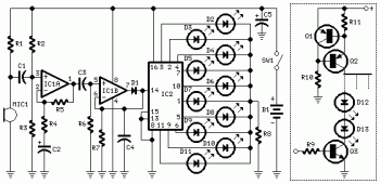
10 Dancing LEDs ElectronicCircuit Based On The LM358 IC
The following circuit illustrates a Dancing LEDs electronic circuit diagram. This circuit is based on the LM358 integrated circuit. Features: IC1A amplifies the signal.
The Dancing LEDs circuit utilizes the LM358 operational amplifier to create a visually appealing light display. The...

led chaser pwm
This compact circuit operates 8 LEDs directly driven from a PIC microcontroller, accompanied by a single mode control switch. The firmware controls the LEDs using a 5-bit PWM signal, enabling four levels of intensity for each LED channel: off, dim,...

Beat frequency indicator
This circuit utilizes LEDs to visualize the beat frequency generated by two-tone oscillators. At any given moment, only one LED is illuminated, and the perceived rotation of the light dot accurately reflects the beat frequency. When f1 is greater than...