


Deglitcher
#deglitcher
#D/A converters
#transient
#digital
#logic
#signal conditioning
#electronics
#glitch removal

Description: Glitch is a commonly used term among electronics professionals that refers to an unwanted transient condition. In digital-to-analog (D/A) converters, this term has gained semi-official recognition for an output transient that occurs when the addressed digital input changes. The sample-and-hold amplifier functions both as a buffer amplifier and as a glitch remover, delaying the output by half a clock cycle. Additionally, the sample-and-hold circuit can be utilized to eliminate various types of glitches within a system. If a delayed sample pulse is necessary, it can be produced using a dual monostable multivibrator integrated circuit (IC).
In electronic systems, glitches can significantly affect performance, particularly in D/A converters where accurate signal representation is critical. The transient condition, or glitch, occurs due to rapid changes in the digital input, leading to momentary output instability. To mitigate this, the sample-and-hold amplifier plays a crucial role. By capturing the input signal at a specific moment and holding that value, it effectively buffers the output, minimizing the impact of any transient changes.
The sample-and-hold amplifier's dual functionality as a glitch remover is particularly noteworthy. By delaying the output by half a clock cycle, it allows the system to stabilize before presenting a new output value. This delay is essential for maintaining signal integrity, especially in high-speed applications where timing is critical.
Furthermore, the versatility of the sample-and-hold circuit extends to its ability to address various glitch types across different systems. By carefully selecting the timing and operation of the sample-and-hold, engineers can design circuits that are resilient to transient disturbances.
In scenarios where a delayed sample pulse is required, a dual monostable multivibrator IC can be employed. This IC generates precise timing pulses, which can be utilized to synchronize the sample-and-hold operation with the overall system clock. By ensuring that the sample pulse aligns with the desired timing, the multivibrator enhances the circuit's ability to manage glitches effectively.
In summary, the integration of sample-and-hold amplifiers and dual monostable multivibrator ICs in electronic designs provides a robust solution for managing glitches, ensuring reliable performance in digital-to-analog conversion and other sensitive applications. Glitch has been a universal slang expression among electronics people for an unwanted transient condition. In D/A converters, th e word has achieved semiofficial status for an output transient, which occurs when the digital input addressed is changed. The sample/hold amplifier does double duty, serving as a buffer amplifier as well as a glitch remover, delaying the output by 1/2-clock cycle.
The sample/hold can be used to remove many other types of glitches in a system. If a delayed sample pulse is required, it can be generated using a dual monostable multivibrator IC.
In electronic systems, glitches can significantly affect performance, particularly in D/A converters where accurate signal representation is critical. The transient condition, or glitch, occurs due to rapid changes in the digital input, leading to momentary output instability. To mitigate this, the sample-and-hold amplifier plays a crucial role. By capturing the input signal at a specific moment and holding that value, it effectively buffers the output, minimizing the impact of any transient changes.
The sample-and-hold amplifier's dual functionality as a glitch remover is particularly noteworthy. By delaying the output by half a clock cycle, it allows the system to stabilize before presenting a new output value. This delay is essential for maintaining signal integrity, especially in high-speed applications where timing is critical.
Furthermore, the versatility of the sample-and-hold circuit extends to its ability to address various glitch types across different systems. By carefully selecting the timing and operation of the sample-and-hold, engineers can design circuits that are resilient to transient disturbances.
In scenarios where a delayed sample pulse is required, a dual monostable multivibrator IC can be employed. This IC generates precise timing pulses, which can be utilized to synchronize the sample-and-hold operation with the overall system clock. By ensuring that the sample pulse aligns with the desired timing, the multivibrator enhances the circuit's ability to manage glitches effectively.
In summary, the integration of sample-and-hold amplifiers and dual monostable multivibrator ICs in electronic designs provides a robust solution for managing glitches, ensuring reliable performance in digital-to-analog conversion and other sensitive applications. Glitch has been a universal slang expression among electronics people for an unwanted transient condition. In D/A converters, th e word has achieved semiofficial status for an output transient, which occurs when the digital input addressed is changed. The sample/hold amplifier does double duty, serving as a buffer amplifier as well as a glitch remover, delaying the output by 1/2-clock cycle.
The sample/hold can be used to remove many other types of glitches in a system. If a delayed sample pulse is required, it can be generated using a dual monostable multivibrator IC.

Digital-ir-transmitter
Gates U1a and U1b are configured as a low-frequency oscillator. The output waveform at pin 11 is nonsymmetrical, with the positive portion of the signal comprising only 20% of the time period. Diode D1, a 1N914 general-purpose unit, along with...

Simple Digital Logic Probe Circuit
The design of the digital logic probe centers around a pair of complementary bipolar transistors, which, in this application, are used as electronic switches.
The digital logic probe is a diagnostic tool utilized for testing and analyzing digital circuits. The core...
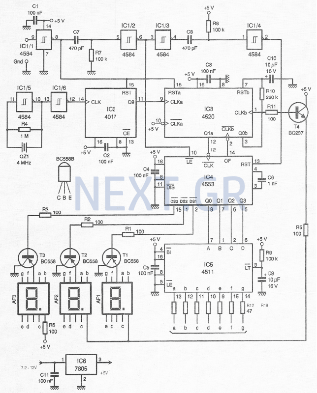
High Precision Digital Pulse Meter Circuit
This compact device, designed primarily for modelers, provides instantaneous readings of pulse duration in milliseconds (ms). It can measure servomotor positions, typically ranging from 1 ms to 2 ms, and can also perform repetitive or non-pulsed measurements, such as the...

Homemade Digital CALL-ID English Version
The reason for this project was to facilitate a quick installation for a local friend 10 km away, enabling the start of real-life testing to identify and resolve bugs and problems before releasing it to other users. The software is...

ADT70 internal functional block diagram
The ADI I70 is a signal conditioning integrated circuit designed for RTD/PRTD applications, particularly suitable for 1K and 100Ω platinum RTDs (PRTDs). The ADT70 features an integrated instrumentation amplifier, an operational amplifier, a 2.5V reference power supply, and a matching...

Digital Vom Phase Meter
The phase-angle meter operates with both analog and digital inputs. A digital voltmeter (DVM) serves as the readout device. The output is 1 mV per degree, with a full-scale output of 360 mV corresponding to 360 degrees. The MC1404 precision...
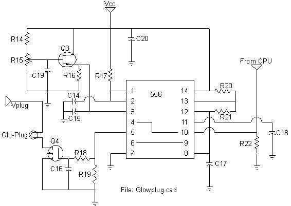
Logic adjustable Glow-Plug drive
All of my turbine starts before the research on the ECU involved a very successful spark ignition. I thought (only briefly) of trying to add spark ignition to the ECU, but the mixture of delicate logic circuitry and perhaps 30,000V...
Logic adjustable Glow-Plug drive
All of my turbine starts before the research on the ECU involved a very successful spark ignition. I thought (only briefly) of trying to add spark ignition to the ECU, but the mixture of delicate logic circuitry and perhaps 30,000V...

Digital pulse width measurement circuit diagram CD4518 and CD4069 the
A digital pulse width measurement circuit is presented. It operates with a 100 kHz reference frequency to count the pulse width of the input signal. The count value represents the measured pulse width displayed on four seven-segment LED displays. The...