


digital electronic lock

Description: The digital lock utilizes four common logic integrated circuits (ICs) to manage a relay activation by inputting a four-digit code via a keypad. The initial four outputs from the CD4017 decade counter (pins 3, 2, 4, and 7) are combined with the digits from the keypad. As the keys are pressed in the correct sequence, the counter progresses.
The digital lock circuit is designed to enhance security by requiring a specific four-digit code for relay activation. The main components include a keypad, a CD4017 decade counter, and a relay driver circuit. The keypad typically consists of a matrix arrangement of buttons, where each button corresponds to a specific digit. When a button is pressed, it sends a signal to the CD4017 counter.
The CD4017 counter is a decade counter that counts from 0 to 9. It has ten outputs, but only the first four outputs (pins 3, 2, 4, and 7) are utilized in this application. Each output corresponds to a specific digit in the code. The outputs are connected to a logic gate configuration that ensures only the correct sequence of inputs can advance the counter. This is achieved through the use of AND gates, which require multiple inputs to be high (logic level '1') simultaneously.
Once the correct sequence of digits is entered, the CD4017 counter advances to the final output, which activates the relay. The relay can then control a larger load, such as a door lock or alarm system, providing a physical mechanism for locking or unlocking based on the entered code.
To ensure reliability, debounce circuits may be implemented to filter out noise from the keypad inputs, preventing false triggering from mechanical bounce when buttons are pressed. Additionally, a reset mechanism can be integrated to reset the counter if an incorrect digit is entered, requiring the user to start over.
Overall, this digital lock circuit is a practical application of basic logic ICs and provides a straightforward yet effective method for securing access through electronic means.The digital lock shown below uses 4 common logic ICs to allow controlling a relay by entering a 4 digit number on a keypad. The first 4 outputs from the CD4017 decade counter (pins 3,2,4,7) are gated together with 4 digits from a keypad so that as the keys are depressed in the correct order, the counter will advance..
The digital lock circuit is designed to enhance security by requiring a specific four-digit code for relay activation. The main components include a keypad, a CD4017 decade counter, and a relay driver circuit. The keypad typically consists of a matrix arrangement of buttons, where each button corresponds to a specific digit. When a button is pressed, it sends a signal to the CD4017 counter.
The CD4017 counter is a decade counter that counts from 0 to 9. It has ten outputs, but only the first four outputs (pins 3, 2, 4, and 7) are utilized in this application. Each output corresponds to a specific digit in the code. The outputs are connected to a logic gate configuration that ensures only the correct sequence of inputs can advance the counter. This is achieved through the use of AND gates, which require multiple inputs to be high (logic level '1') simultaneously.
Once the correct sequence of digits is entered, the CD4017 counter advances to the final output, which activates the relay. The relay can then control a larger load, such as a door lock or alarm system, providing a physical mechanism for locking or unlocking based on the entered code.
To ensure reliability, debounce circuits may be implemented to filter out noise from the keypad inputs, preventing false triggering from mechanical bounce when buttons are pressed. Additionally, a reset mechanism can be integrated to reset the counter if an incorrect digit is entered, requiring the user to start over.
Overall, this digital lock circuit is a practical application of basic logic ICs and provides a straightforward yet effective method for securing access through electronic means.The digital lock shown below uses 4 common logic ICs to allow controlling a relay by entering a 4 digit number on a keypad. The first 4 outputs from the CD4017 decade counter (pins 3,2,4,7) are gated together with 4 digits from a keypad so that as the keys are depressed in the correct order, the counter will advance..

GS500 Horn
A relay is an electrically operated switch that utilizes a coil to create magnetism, which closes the contacts of the switch. In automotive applications, a 12V signal through the coil allows 12V to flow through the switch contacts. The advantage...

Relay protection circuit
Operating power protection devices can be categorized into two types: DC power supply operation and AC operation. AC operating power is favored due to its lower investment costs, simpler operation, and reliable secondary circuit maintenance, making it widely used in...
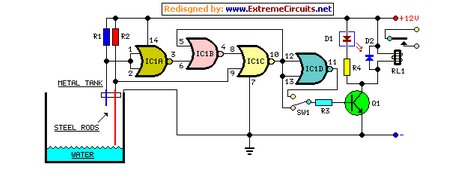
Water Pump Relay Controller Circuit Schematic
This circuit utilizes a relay to control a water pump for automatic level regulation of a water reservoir or well. The shorter steel rod acts as a high water sensor, while the longer rod serves as a low water sensor....

Counter circuit diagram of the digital circuit
The digital counter circuit described utilizes an infrared signal to detect moving targets, making it suitable for counting small devices on a production line as they move along a conveyor belt. This circuit can also be employed for various other...

Lantern making use of a relay control circuit
220V mains electricity is sent through a 0.33 µF capacitor (Ci) and a 50 kΩ resistive drop. A bridge rectifier composed of diodes D1 to D4 converts the AC voltage to DC. After passing through a 100 µF capacitor for...

relay Do I need a protection diode here
An automotive relay is being analyzed, which exhibits a more complex wiring configuration than typical relays. The diagram indicates that the B/G line maintains a high signal if certain conditions are met, specifically when the engine temperature is excessively high,...

Secure lock circuit (CD4017) schematic
The circuit consists of a two and four decimal counter CD4017 used in conjunction with a password switch. It is composed of the output terminals from the key switch logic combination of components, which provide another feature of the electronic...

Single Transistor Relay Toggle Circuit
The circuit requires a double pole, double throw relay in conjunction with a single transistor to allow toggling the relay with a momentary push button. One set of relay contacts is used to control the load, while the other is...

MEM 800
This website provides schematics and instructions for constructing a keypad circuit that can be interfaced with a PC using an 8255 PC interface board. The keypad is directly connected to a client computer, which transmits information from the keypad over...