


Digital IC Tester for 74 series
#digital IC tester
#74 series
#microcontroller
#ZIF socket
#truth table
#digital logic design
#integrated circuits
#testing
#laboratory
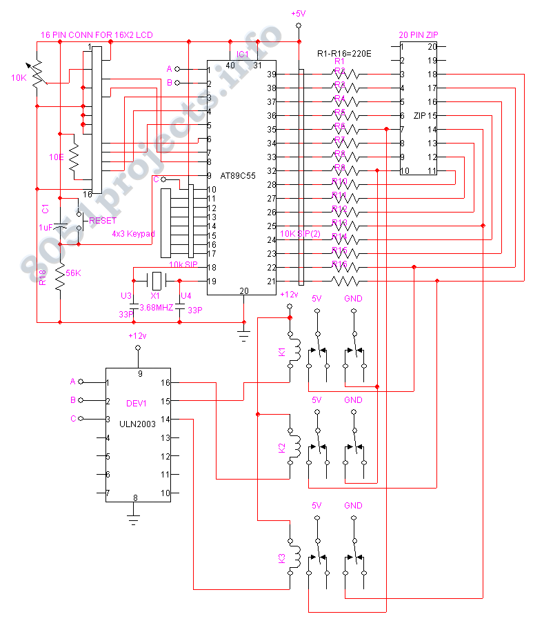
Description: The chip tester verifies the functionality and timing of a variety of 7400 series integrated circuits. Students taking Digital Logic Design Lab use these chips often in their laboratory. The IC to be tested should be placed on the ZIF socket, and the Microcontroller prompts the user to enter the IC number of the chip to be tested. After entering it, the microcontroller will check the IC as per the truth table of the IC which is stored in its ROM. It will check each and every pin of the IC and produce the output detail, like "Gate 1 is good," "Gate is Bad," "Counter 1 is Good," etc.
The circuit design of the chip tester comprises several key components, including a Zero Insertion Force (ZIF) socket for secure and easy insertion of the ICs, a microcontroller for processing and controlling the testing sequence, and a digital display for outputting the results. The ZIF socket allows for the easy placement and removal of ICs without the risk of damaging the pins, which is crucial in a laboratory setting where multiple tests may be performed.
The microcontroller serves as the central processing unit of the tester, equipped with a program that includes the truth tables for various 7400 series ICs stored in its Read-Only Memory (ROM). Upon inserting an IC into the ZIF socket, the user is prompted to input the specific IC number through a keypad or similar input device. The microcontroller then accesses the corresponding truth table for that IC and begins the testing process.
During testing, the microcontroller systematically checks each pin of the IC against the expected logic states defined in the truth table. This involves sending test signals to the IC and monitoring the responses on each pin. The microcontroller evaluates the output and determines the operational status of each gate or function within the IC.
The results are then displayed on a digital output screen, providing clear feedback on the condition of the IC. The output may include detailed messages such as "Gate 1 is good," indicating proper functionality, or "Gate is Bad," suggesting a failure in that specific component. This detailed output assists students and engineers in diagnosing issues with ICs, facilitating a better understanding of digital logic design and integrated circuit behavior.
In summary, the chip tester is an essential tool in educational and practical applications, enabling users to verify the integrity and functionality of 7400 series integrated circuits efficiently.The chip tester verifies the functionality and timing of a variety of 7400 series integrated circuits. Students taking Digital Logic Design Lab, Use these chips often in their laboratory. The IC to be tested should be placed on the ZIF socket and the Microcontroller prompts the user to enter the IC number of the chip to be tested.
After entering it the microcontroller will check the IC as per the truth table of the IC which is stored in its ROM. It will check each aand every pin of the IC and produce the Output detaily. Like "Gate 1 is good", "Gate is Bad", "Counter 1 is Good" etc
The circuit design of the chip tester comprises several key components, including a Zero Insertion Force (ZIF) socket for secure and easy insertion of the ICs, a microcontroller for processing and controlling the testing sequence, and a digital display for outputting the results. The ZIF socket allows for the easy placement and removal of ICs without the risk of damaging the pins, which is crucial in a laboratory setting where multiple tests may be performed.
The microcontroller serves as the central processing unit of the tester, equipped with a program that includes the truth tables for various 7400 series ICs stored in its Read-Only Memory (ROM). Upon inserting an IC into the ZIF socket, the user is prompted to input the specific IC number through a keypad or similar input device. The microcontroller then accesses the corresponding truth table for that IC and begins the testing process.
During testing, the microcontroller systematically checks each pin of the IC against the expected logic states defined in the truth table. This involves sending test signals to the IC and monitoring the responses on each pin. The microcontroller evaluates the output and determines the operational status of each gate or function within the IC.
The results are then displayed on a digital output screen, providing clear feedback on the condition of the IC. The output may include detailed messages such as "Gate 1 is good," indicating proper functionality, or "Gate is Bad," suggesting a failure in that specific component. This detailed output assists students and engineers in diagnosing issues with ICs, facilitating a better understanding of digital logic design and integrated circuit behavior.
In summary, the chip tester is an essential tool in educational and practical applications, enabling users to verify the integrity and functionality of 7400 series integrated circuits efficiently.The chip tester verifies the functionality and timing of a variety of 7400 series integrated circuits. Students taking Digital Logic Design Lab, Use these chips often in their laboratory. The IC to be tested should be placed on the ZIF socket and the Microcontroller prompts the user to enter the IC number of the chip to be tested.
After entering it the microcontroller will check the IC as per the truth table of the IC which is stored in its ROM. It will check each aand every pin of the IC and produce the Output detaily. Like "Gate 1 is good", "Gate is Bad", "Counter 1 is Good" etc

Microcontroller interfacing with RS 232
Standard serial interfacing of a microcontroller (TTL) with a PC or any RS232C standard device requires a TTL to RS232 level converter. A MAX232 is used for this purpose. It provides a 2-channel RS232C port and requires external 10µF capacitors.
The...

Robot Motor Control Schematic
The schematic for controlling the motors is divided into three main sections, each serving a distinct function. The primary components featured in the schematic include the PIC 18F252 microcontroller, the SN754410 motor driver, and 2N2222 transistors. At the top of...

Eight-digit-microprocessor-display
The display interface utilizes the ICM7218A/B in conjunction with an 8048 family microcontroller. An 8-bit data bus (DBO/DB7-IDO/ID7) facilitates the transfer of control and data information to the 7218 display interface during successive WRITE pulses. The mode input pins on...

Water Level controller
The microcontroller-based water level controller and motor protector manages the on and off states of the motor based on the water level in the overhead tank (OHT). It regulates the tank's water level through a microcontroller, thereby providing automatic protection...

Power supplies for microcontroller based projects
This document discusses the use of small microcontrollers, such as those from the PIC and Atmel series, which typically operate at 5V and require less than 100mA for complete system functionality. Some PICs can function at lower voltages, such as...

Jet
The microcontroller is able to make about 7000 complete line-following decisions per second, which is almost 7 decisions per millimeter when the robot is going full speed. By upping the clock, unrolling loops, and removing my wireless debugging and extraneous...

Miniature Real-time Controller
This is my long history the device that controls my home's night light, air-conditioner, etc. The device is a Miniature Real-time Controller. The circuit uses only three chips, a 89C2051, DS275 (or MAX232), and 74LS07 open collector driver. The scheduler...

87C51 Selling Leads
This circuit utilizes an 87C57 microcontroller along with several peripherals to convert X-10 power-line carrier-code formats from a personal computer for use with an X-10 power-line interface in a home control system. Software details can be found in the reference....

Metal detector circuit
The project demonstration has been successfully completed, with the only remaining task being the final project report due on June 15, which will be integrated with a conference paper. This update marks the last entry in the electronic notebook, although...