


Digital Mixer
#digital mixer
#Schmitt trigger
#exclusive-OR gates
#RC time-delay
#4583B
#logic gates
#signal processing
#digital circuits

Description: A simple digital mixer uses two dual-Schmitt triggers (4583B) and three exclusive-OR gates, incorporating an RC time-delay circuit to allow for easy adjustment of the output signal pulse width. The exclusive-OR gates can also function independently as a symmetrical frequency doubler. In this configuration, a signal passing through the Schmitt triggers experiences a delay of t, which is calculated as RC ln(V+/Vt), where V+ and Vin represent the positive and negative threshold voltages of the triggers. For optimal operation, the same time delay must be applied to signals f1 and f2, and this delay should be less than 50% of the period of f1. If f1 is more than twice the value of f2, the output of the circuit will yield the difference between the two signals (i.e., f1 - f2).
The described digital mixer circuit utilizes two dual-Schmitt triggers (part number 4583B) to process input signals, enhancing signal integrity by providing hysteresis. This characteristic is particularly beneficial in noisy environments, where it helps to clean up the input signals. The inclusion of three exclusive-OR gates allows for versatile functionality, enabling both mixing and frequency doubling operations.
The RC time-delay circuit is a critical component, allowing for the adjustment of the output pulse width. The time delay, denoted as t, is determined by the resistor-capacitor (RC) combination and is expressed as t = RC ln(V+/Vt). Here, V+ is the upper threshold voltage and Vt is the lower threshold voltage of the Schmitt triggers. This relationship ensures that the timing of the signals f1 and f2 is synchronized, which is essential for the accurate subtraction of these signals.
It is important that the time delay applied to both signals f1 and f2 is less than half the period of f1 to maintain signal integrity and avoid distortion in the output. The condition that f1 must be greater than twice the value of f2 ensures that the circuit can effectively produce a meaningful output, which is the difference between the two input signals (f1 - f2). This output can be utilized in various applications, such as audio mixing or signal processing, where precise control over signal characteristics is required.
Overall, the design of this digital mixer circuit is efficient and adaptable, making it suitable for a range of electronic applications that require signal manipulation and processing. A simple digital mixer, based on two dual-Schmitt triggers (4583B) and three exclusive-OR gates, uses an RC time-delay circui t to permit easy adjustment of the output-signal pulse width. The exclusive-OR gates can also be used separately as a symmetrical frequency doubler. As shown, a signal passing through the Schmitt triggers is delayed by t, a value equal to RC In (y#/ Vt„), where V^ and Vin are the positive and negative threshold voltages of the triggers. To function properly, the same time delay must be introduced to signals f1 and f2. Also, the time delay must be less than 50% of the period of fl. Provided that fl is more than twice the value of f2, the output of the circuit will equal the difference of the two signals (i.e., fl-f2).
The described digital mixer circuit utilizes two dual-Schmitt triggers (part number 4583B) to process input signals, enhancing signal integrity by providing hysteresis. This characteristic is particularly beneficial in noisy environments, where it helps to clean up the input signals. The inclusion of three exclusive-OR gates allows for versatile functionality, enabling both mixing and frequency doubling operations.
The RC time-delay circuit is a critical component, allowing for the adjustment of the output pulse width. The time delay, denoted as t, is determined by the resistor-capacitor (RC) combination and is expressed as t = RC ln(V+/Vt). Here, V+ is the upper threshold voltage and Vt is the lower threshold voltage of the Schmitt triggers. This relationship ensures that the timing of the signals f1 and f2 is synchronized, which is essential for the accurate subtraction of these signals.
It is important that the time delay applied to both signals f1 and f2 is less than half the period of f1 to maintain signal integrity and avoid distortion in the output. The condition that f1 must be greater than twice the value of f2 ensures that the circuit can effectively produce a meaningful output, which is the difference between the two input signals (f1 - f2). This output can be utilized in various applications, such as audio mixing or signal processing, where precise control over signal characteristics is required.
Overall, the design of this digital mixer circuit is efficient and adaptable, making it suitable for a range of electronic applications that require signal manipulation and processing. A simple digital mixer, based on two dual-Schmitt triggers (4583B) and three exclusive-OR gates, uses an RC time-delay circui t to permit easy adjustment of the output-signal pulse width. The exclusive-OR gates can also be used separately as a symmetrical frequency doubler. As shown, a signal passing through the Schmitt triggers is delayed by t, a value equal to RC In (y#/ Vt„), where V^ and Vin are the positive and negative threshold voltages of the triggers. To function properly, the same time delay must be introduced to signals f1 and f2. Also, the time delay must be less than 50% of the period of fl. Provided that fl is more than twice the value of f2, the output of the circuit will equal the difference of the two signals (i.e., fl-f2).
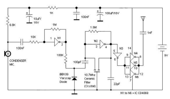
Logic Gates FM Transmitter Circuit
Logic Gates FM Transmitter Circuit Electronic Circuit Schematic Wiring Diagram.
The FM transmitter circuit utilizing logic gates is a fundamental electronic design that operates by modulating a carrier frequency with an audio signal. This circuit typically consists of various logic gates...
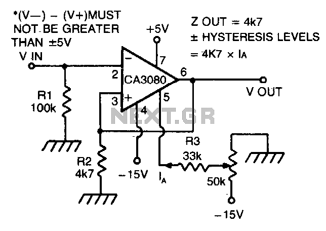
Schmitt trigger with programmable hysteresis
The CA 3088 is utilized as a versatile Schmitt trigger. The magnitude of the hysteresis levels is determined by the current (Ia) flowing out of the amplifier's output and through resistor R2. An increase in Ia results in an increase...

Schmitt Trigger Circuit
This Schmitt trigger circuit is emitter coupled and provides a simple comparator action. The 2N3069 JFET places very little loading on the measured input. Schmitt trigger, emitter coupled, simple comparator, 2N3565, distinct hysteresis loop.
The described circuit utilizes an emitter-coupled Schmitt...

Schmitt Inverter
The Schmitt trigger is a specialized circuit that functions as a switch, altering its state at two distinct voltage thresholds known as the upper and lower thresholds, or the positive and negative-going thresholds. The difference between these two threshold levels...
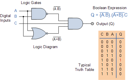
Combinational Logic Circuits using Logic Gates
Electronics tutorial on combinational logic circuits that utilize logic gates to create multiplexers, encoders, and solid-state switches.
Combinational logic circuits are fundamental components in digital electronics, characterized by their ability to produce outputs based solely on the current inputs, without any...

electrical engineering logic gates
Design a circuit with four single-bit inputs X, Y, T, and Z, and a single-bit output E. A two-bit control code word S0S1 determines which of the four inputs is sent to the output (the selection code is not unique)....
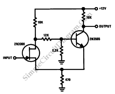
Discrete Schmitt Trigger
This is a Schmitt trigger circuit. This circuit produces a simple comparator action. It is emitter-coupled. This circuit has a distinct hysteresis loop.
The Schmitt trigger circuit is a fundamental electronic component utilized for signal conditioning, providing a means to convert...

Schmitt trigger crystal oscillator
A Schmitt trigger provides effective squaring of the output, sometimes eliminating the need for an additional output stage.
A Schmitt trigger is a type of comparator circuit that incorporates hysteresis, which allows it to provide clean, stable output transitions. This characteristic...

The SC (Schmitt Comparator) Head
I'll eventually post an explanation, but in the meantime, here it is. Meanwhile, a slightly refined version (with flashing LEDs to indicate "lock") was posted a few weeks later:
The provided description indicates a project involving a circuit that utilizes flashing...