


DIY 2 Layer Boards Circuit
#74LS164
#555 timer
#Eagle Layout Editor
#schematic design
#two layer board
#logic IC
#timer circuit
#PCB design

Description: For the two-layer board schematic, six core integrated circuits (ICs) will be utilized: four 74LS164 shift registers and two 555 timers. The schematic will be constructed using the Eagle Layout Editor, as all required components are available in its library. The first 555 timer is configured with two 10k ohm resistors and a 47µF capacitor, generating an output signal that oscillates between 0V and 5V every second. This clock signal will shift data to the 74LS164 shift registers at a rate of one bit every second. The output signal from the second 555 timer will be connected to the data input of the 74LS164. This timer is set up with a 1k ohm resistor, a 100µF capacitor, and a 100k ohm trimpot (variable resistor). Adjusting the trimpot from 100k ohms to 0 ohms alters the output frequency of the 555 timer from 14 Hz to 0.1 Hz. The shift registers will receive data input from the slower clock, which is triggered by transitions of the faster clock from 0V to 5V. Consequently, the data input remains constant unless the trimpot is adjusted, which changes the speed of the faster clock. If the slower clock exceeds the rate of the faster clock, the digital data input will consistently register as high (1).
The circuit design incorporates two distinct timing mechanisms that work in tandem to control the flow of data to the shift registers. The first 555 timer serves as a primary clock generator, providing a stable, periodic signal that dictates the timing for data shifting. The configuration of two 10k ohm resistors and a 47µF capacitor establishes a time constant that results in a one-second pulse width, effectively creating a 1 Hz clock signal. This signal is crucial for the operation of the 74LS164 shift registers, allowing them to process incoming data at regular intervals.
The second 555 timer operates as a variable frequency generator, offering flexibility in the data input rate. The combination of a 1k ohm resistor, a 100µF capacitor, and the 100k ohm trimpot allows for fine-tuning of the output frequency. By adjusting the trimpot, the output frequency can be varied from 14 Hz (when the trimpot is at 100k ohms) to as low as 0.1 Hz (when the trimpot is at 0 ohms). This feature enables dynamic control over the data input rate to the shift registers, allowing for various operational scenarios.
The interaction between the two clocks is essential for the functionality of the circuit. The slower clock, dictated by the first 555 timer, ensures that data is shifted into the shift registers at a controlled rate. The faster clock, influenced by the second 555 timer, determines the timing of the data input. In cases where the slower clock exceeds the frequency of the faster clock, the data input will remain high, effectively saturating the shift registers with a constant high signal. This design illustrates the importance of timing in digital circuits, where precise control over data flow can significantly impact overall performance and functionality.For the 2 layer board schematic, we`ll use 6 core IC`s: 4 74LS164`s and 2 555 Timers. The schematic will be built using Eagle Layout Editor since all the parts I need exist in their library. The final schematic can be seen below, click on the picture for the full view. Two 555 timers are used in this circuit. The first 555 timer uses two 10k © re sistors and a 47uF capacitor, which creates an output signal that alternates between +0v and +5v every second. This clock signal will therefore shift in data to the 74LS164`s 1 bit every 1 second. The second 555 timer output signal will be fed into the data input of the 74LS164. It uses one 1k © resistor, a 100uF capacitor and a 100k © trimpot (variable resistor). When the trimpot is varied from 100k © to 0 ©, the 555 timer output frequency changes from 14 Hz to 0.
1 Hz. These shift registers will receive data input from the slower clock, which is input whenever the faster clock transitions from +0v to +5v. This means the data input will be constant since the two clocks work off of one another. Only when the trimpot is changed will the data input change, as this makes the faster clock speed up or slow down.
If the slow clock ever becomes faster than the fast clock, the digital data input will always be seen as 1.
The circuit design incorporates two distinct timing mechanisms that work in tandem to control the flow of data to the shift registers. The first 555 timer serves as a primary clock generator, providing a stable, periodic signal that dictates the timing for data shifting. The configuration of two 10k ohm resistors and a 47µF capacitor establishes a time constant that results in a one-second pulse width, effectively creating a 1 Hz clock signal. This signal is crucial for the operation of the 74LS164 shift registers, allowing them to process incoming data at regular intervals.
The second 555 timer operates as a variable frequency generator, offering flexibility in the data input rate. The combination of a 1k ohm resistor, a 100µF capacitor, and the 100k ohm trimpot allows for fine-tuning of the output frequency. By adjusting the trimpot, the output frequency can be varied from 14 Hz (when the trimpot is at 100k ohms) to as low as 0.1 Hz (when the trimpot is at 0 ohms). This feature enables dynamic control over the data input rate to the shift registers, allowing for various operational scenarios.
The interaction between the two clocks is essential for the functionality of the circuit. The slower clock, dictated by the first 555 timer, ensures that data is shifted into the shift registers at a controlled rate. The faster clock, influenced by the second 555 timer, determines the timing of the data input. In cases where the slower clock exceeds the frequency of the faster clock, the data input will remain high, effectively saturating the shift registers with a constant high signal. This design illustrates the importance of timing in digital circuits, where precise control over data flow can significantly impact overall performance and functionality.For the 2 layer board schematic, we`ll use 6 core IC`s: 4 74LS164`s and 2 555 Timers. The schematic will be built using Eagle Layout Editor since all the parts I need exist in their library. The final schematic can be seen below, click on the picture for the full view. Two 555 timers are used in this circuit. The first 555 timer uses two 10k © re sistors and a 47uF capacitor, which creates an output signal that alternates between +0v and +5v every second. This clock signal will therefore shift in data to the 74LS164`s 1 bit every 1 second. The second 555 timer output signal will be fed into the data input of the 74LS164. It uses one 1k © resistor, a 100uF capacitor and a 100k © trimpot (variable resistor). When the trimpot is varied from 100k © to 0 ©, the 555 timer output frequency changes from 14 Hz to 0.
1 Hz. These shift registers will receive data input from the slower clock, which is input whenever the faster clock transitions from +0v to +5v. This means the data input will be constant since the two clocks work off of one another. Only when the trimpot is changed will the data input change, as this makes the faster clock speed up or slow down.
If the slow clock ever becomes faster than the fast clock, the digital data input will always be seen as 1.
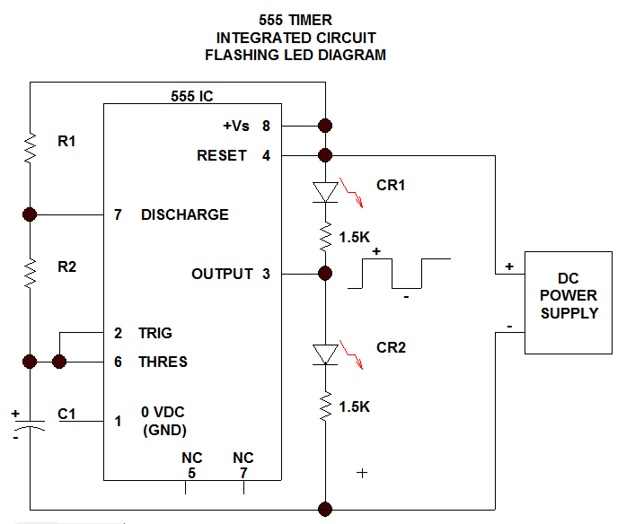
railroad crossing ledprojects
This section discusses one of the most useful Integrated Circuits (IC), commonly known as the 555 Timer chip. It is important to note that ICs...
The 555 Timer IC is a versatile and widely used component in electronic circuits, primarily known...

Fundamentals of Electrical Engineering and Monostable Multivibrator
This is one of the most basic 555 circuits. This circuit is part of the chip's datasheet, complete with the math needed to design to specification, and is one of the reasons a 555 is referred to as a timer....
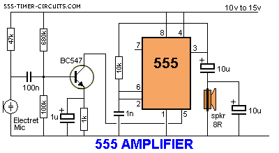
simple 555 amplifier
The 555 timer can function as an amplifier, operating similarly to pulse-width modulation. The component values lead the 555 to oscillate at approximately 66 kHz, a frequency to which the speaker does not respond. Instead, the speaker reacts to the...

555 DC Voltage Doubler Circuit
This DC voltage doubler circuit generates a voltage that is double its supply voltage. It is advantageous when a higher voltage level is required from a single lower voltage power supply. Due to the low current consumption in such applications,...

police siren pcb
This circuit generates a sound akin to a police siren. It utilizes two 555 timer integrated circuits (ICs) configured as astable multivibrators. The frequency is regulated by pin 5 of the IC. The first IC operates at approximately 1Hz, where...

Auto light controller
A 555 timer integrated circuit (IC) functions in one-shot mode, triggered by light exposure to photoresistors. These photoresistors typically exhibit a resistance in the range of several megohms, which decreases to several hundred ohms under light conditions, allowing current from...

Inductive switching power supply circuit diagram
The circuit consists of a 555 timer configured as an astable multivibrator along with resistors R1 and R2 and capacitor C1. It generates an oscillation frequency of approximately 10 kHz with a duty cycle close to 50%. Transistors VT2 and...

555 1 Hz pulse generator
A simple buzzer is being converted into an oscillating buzzer to produce a sound similar to that of an automobile's reverse indicator. The schematic provided is borrowed from electroschematics.com. The intention is to replace the LED in the circuit with...

bistable multivibrator using ic 555
By applying a "LOW" signal to the Trigger input (pin 2) while the switch is in the Set position, the output state changes to "HIGH". Conversely, applying a "LOW" signal to the Reset input (pin 4) while the switch is...