


Examples of Digital Filters
#digital filters
#DSP
#low-pass filter
#noise reduction
#signal processing
#multiplexing
#electronics
#filter design
#analog electronics
#frequency response

Description: Digital filters are powerful yet user-friendly, contributing to the popularity of digital signal processing (DSP). For example, a low-pass filter with a cutoff frequency of 1 kHz can be implemented in analog electronics. This method is often utilized for noise reduction or for separating multiplexed signals. Alternatively, a signal can be digitized and processed using a digital filter. If the signal is sampled at 10 kHz, a digital filter can be implemented through a simple program. The program filters 5000 samples using a 101-point windowed-sinc filter, yielding 4900 samples of filtered data. The process begins by initializing arrays for the input signal, output signal, and filter kernel. The cutoff frequency is set to 0.1 of the sampling rate, and the filter kernel length is defined. The filter kernel is calculated using a loop, and the signal is filtered through convolution. Most digital filters can be implemented with only a few dozen lines of code. Comparisons between analog and digital filters reveal significant differences in performance. The analog filter exhibits a 6% ripple in the passband, while the digital filter maintains a flat response within 0.02%. The flatness of analog filters is constrained by the precision of resistors and capacitors, whereas digital filters are primarily limited by round-off error, achieving much flatter responses. Analyzing the frequency responses on a logarithmic scale demonstrates that digital filters outperform analog filters in terms of roll-off and stopband attenuation. Enhancing the performance of analog filters is challenging, while digital filters can be modified easily to improve performance significantly. For instance, a digital filter can achieve a gain of 1 +/- 0.0002 from DC to 999 Hz, with a gain of less than 0.0002 for frequencies above 1001 Hz, with a rapid transition of about 1 Hz. Another digital filter can achieve a stopband attenuation of -150 dB, demonstrating the superior capabilities of digital filters compared to analog solutions.
Digital filters offer a versatile and efficient means of signal processing, allowing for precise manipulation of frequency responses. The implementation of a low-pass filter using a windowed-sinc function exemplifies the effectiveness of digital methodologies. The programmatic approach to filter design facilitates rapid adjustments and enhancements, enabling engineers to tailor filters to specific requirements with minimal effort.
The initialization phase of the program sets up the necessary arrays to hold the input signal, output signal, and filter kernel, ensuring that all data is organized for processing. The filter kernel is generated through a mathematical computation that takes into account the desired cutoff frequency and the length of the kernel. This kernel is crucial for the convolution process, which is the core of the filtering operation.
During the convolution phase, the program iterates through the input signal, applying the filter kernel to produce the output signal. Each output sample is computed as the weighted sum of the input samples, with the weights determined by the filter kernel. This method allows for effective attenuation of unwanted frequencies while preserving the desired signal components.
The comparison of frequency responses between analog and digital filters highlights the advancements in digital signal processing. Digital filters can achieve remarkable performance metrics, such as minimal ripple and exceptional stopband attenuation, which are often unattainable with analog designs. The ability to scale digital filters easily enhances their utility in various applications, from audio processing to telecommunications.
In conclusion, the transition from analog to digital filtering represents a significant evolution in signal processing technology. The advantages of digital filters, including ease of implementation, superior performance, and flexibility, make them an indispensable tool in modern electronics and communications.Digital filters are incredibly powerful, but easy to use. In fact, this is one of the main reasons that DSP has become so popular. As an example, suppose we need a low-pass filter at 1 kHz. This could be carried out in analog electronics with the following circuit: For instance, this might be used for noise reduction or separating multiplexed sign als. (Chapter 3 describes how to design these analog filters). As an alternative, we could digitize the signal and use a digital filter. Say we sample the signal at 10 kHz. A comparable digital filter is carried out by the following program: 100 `LOW-PASS WINDOWED-SINC FILTER 110 `This program filters 5000 samples with a 101 point windowed-sinc 120 `filter, resulting in 4900 samples of filtered data. 130 ` 140 ` `INITIALIZE AND DEFINE THE ARRAYS USED 150 DIM X[4999] `X[ ] holds the input signal 160 DIM Y[4999] `Y[ ] holds the output signal 170 DIM H[100] `H[ ] holds the filter kernel 180 ` 190 PI = 3.
14159265 200 FC = 0. 1 `The cutoff frequency (0. 1 of the sampling rate) 210 M% = 100 `The filter kernel length 220 ` 230 GOSUB XXXX `Subroutine to load X[ ] with the input signal 240 ` 250 ` `CALCULATE THE FILTER KERNEL 260 FOR I% = 0 TO 100 270 IF (I%-M%/2) = 0 THEN H[I%] = 2*PI*FC 280 IF (I%-M%/2) <> 0 THEN H[I%] = SIN(2*PI*FC * (I%-M%/2) / (I%-M%/2) 290 H[I%] = H[I%] * (0. 54 - 0. 46*COS(2*PI*I%/M%) ) 300 NEXT I% 310 ` 320 `FILTER THE SIGNAL BY CONVOLUTION 330 FOR J% = 100 TO 4999 340 Y[J%] = 0 350 FOR I% = 0 TO 100 360 Y[J%] = Y[J%] + X[J%-I%] * H[I%] 370 NEXT I% 380 NEXT J% 390 ` 400 END As in this example, most digital filters can be implemented with only a few dozen lines of code.
How do the analog and digital filters compare Here are the frequency responses of the two filters: Even though we designed the digital filter to approximately match the analog filter, there are still several significant differences between the two. First, the analog filter has a 6% ripple in the passband, while the digital filter is perfectly flat (within 0.
02%). The analog designer might argue that the ripple can be selected in the design; however, this misses the point. The flatness achievable with analog filters is limited by the accuracy of their resistors and capacitors.
Even if it is designed for zero ripple (a Butterworth filter), analog filters of this complexity will have a residue ripple of, perhaps, 1%. On the other hand, the flatness of digital filters is primarily limited by round-off error, making them hundreds of times flatter than their analog counterparts.
Next, let`s look at the frequency response on a log scale (decibels), as shown below. Again, the digital filter is clearly the victor in both roll-off and stopband attenuation. Even if the analog performance is improved by adding additional stages, it still can`t compete with the digital filter. Imagine you need to improve the performance of the filter by a factor of 100. This would be virtually impossible for the analog circuit, but only requires simple modifications to the digital filter.
For instance, look at the two frequency responses below, a digital filter designed for very fast roll-off, and a digital filter designed for exceptional stopband attenuation. The frequency response on the left has a gain of 1 +/- 0. 0002 from DC to 999 hertz, and a gain of less than 0. 0002 for frequencies above 1001 hertz. The entire transition occurs in only about 1 hertz. The frequency response on the right is equally impressive: the stopband attenuation is -150 dB, one part in 30 million!
Don`t try this with an op amp! As in these examples, digital filters can achieve thousands of times better performance than analog filters. This makes a dramatic difference in how filtering problems are approached. With analog filters, the emphasis is on handling limitations of the electronics, such as the accuracy and stability of the resistors and capacitors.
In comparison, digital filters are
Digital filters offer a versatile and efficient means of signal processing, allowing for precise manipulation of frequency responses. The implementation of a low-pass filter using a windowed-sinc function exemplifies the effectiveness of digital methodologies. The programmatic approach to filter design facilitates rapid adjustments and enhancements, enabling engineers to tailor filters to specific requirements with minimal effort.
The initialization phase of the program sets up the necessary arrays to hold the input signal, output signal, and filter kernel, ensuring that all data is organized for processing. The filter kernel is generated through a mathematical computation that takes into account the desired cutoff frequency and the length of the kernel. This kernel is crucial for the convolution process, which is the core of the filtering operation.
During the convolution phase, the program iterates through the input signal, applying the filter kernel to produce the output signal. Each output sample is computed as the weighted sum of the input samples, with the weights determined by the filter kernel. This method allows for effective attenuation of unwanted frequencies while preserving the desired signal components.
The comparison of frequency responses between analog and digital filters highlights the advancements in digital signal processing. Digital filters can achieve remarkable performance metrics, such as minimal ripple and exceptional stopband attenuation, which are often unattainable with analog designs. The ability to scale digital filters easily enhances their utility in various applications, from audio processing to telecommunications.
In conclusion, the transition from analog to digital filtering represents a significant evolution in signal processing technology. The advantages of digital filters, including ease of implementation, superior performance, and flexibility, make them an indispensable tool in modern electronics and communications.Digital filters are incredibly powerful, but easy to use. In fact, this is one of the main reasons that DSP has become so popular. As an example, suppose we need a low-pass filter at 1 kHz. This could be carried out in analog electronics with the following circuit: For instance, this might be used for noise reduction or separating multiplexed sign als. (Chapter 3 describes how to design these analog filters). As an alternative, we could digitize the signal and use a digital filter. Say we sample the signal at 10 kHz. A comparable digital filter is carried out by the following program: 100 `LOW-PASS WINDOWED-SINC FILTER 110 `This program filters 5000 samples with a 101 point windowed-sinc 120 `filter, resulting in 4900 samples of filtered data. 130 ` 140 ` `INITIALIZE AND DEFINE THE ARRAYS USED 150 DIM X[4999] `X[ ] holds the input signal 160 DIM Y[4999] `Y[ ] holds the output signal 170 DIM H[100] `H[ ] holds the filter kernel 180 ` 190 PI = 3.
14159265 200 FC = 0. 1 `The cutoff frequency (0. 1 of the sampling rate) 210 M% = 100 `The filter kernel length 220 ` 230 GOSUB XXXX `Subroutine to load X[ ] with the input signal 240 ` 250 ` `CALCULATE THE FILTER KERNEL 260 FOR I% = 0 TO 100 270 IF (I%-M%/2) = 0 THEN H[I%] = 2*PI*FC 280 IF (I%-M%/2) <> 0 THEN H[I%] = SIN(2*PI*FC * (I%-M%/2) / (I%-M%/2) 290 H[I%] = H[I%] * (0. 54 - 0. 46*COS(2*PI*I%/M%) ) 300 NEXT I% 310 ` 320 `FILTER THE SIGNAL BY CONVOLUTION 330 FOR J% = 100 TO 4999 340 Y[J%] = 0 350 FOR I% = 0 TO 100 360 Y[J%] = Y[J%] + X[J%-I%] * H[I%] 370 NEXT I% 380 NEXT J% 390 ` 400 END As in this example, most digital filters can be implemented with only a few dozen lines of code.
How do the analog and digital filters compare Here are the frequency responses of the two filters: Even though we designed the digital filter to approximately match the analog filter, there are still several significant differences between the two. First, the analog filter has a 6% ripple in the passband, while the digital filter is perfectly flat (within 0.
02%). The analog designer might argue that the ripple can be selected in the design; however, this misses the point. The flatness achievable with analog filters is limited by the accuracy of their resistors and capacitors.
Even if it is designed for zero ripple (a Butterworth filter), analog filters of this complexity will have a residue ripple of, perhaps, 1%. On the other hand, the flatness of digital filters is primarily limited by round-off error, making them hundreds of times flatter than their analog counterparts.
Next, let`s look at the frequency response on a log scale (decibels), as shown below. Again, the digital filter is clearly the victor in both roll-off and stopband attenuation. Even if the analog performance is improved by adding additional stages, it still can`t compete with the digital filter. Imagine you need to improve the performance of the filter by a factor of 100. This would be virtually impossible for the analog circuit, but only requires simple modifications to the digital filter.
For instance, look at the two frequency responses below, a digital filter designed for very fast roll-off, and a digital filter designed for exceptional stopband attenuation. The frequency response on the left has a gain of 1 +/- 0. 0002 from DC to 999 hertz, and a gain of less than 0. 0002 for frequencies above 1001 hertz. The entire transition occurs in only about 1 hertz. The frequency response on the right is equally impressive: the stopband attenuation is -150 dB, one part in 30 million!
Don`t try this with an op amp! As in these examples, digital filters can achieve thousands of times better performance than analog filters. This makes a dramatic difference in how filtering problems are approached. With analog filters, the emphasis is on handling limitations of the electronics, such as the accuracy and stability of the resistors and capacitors.
In comparison, digital filters are
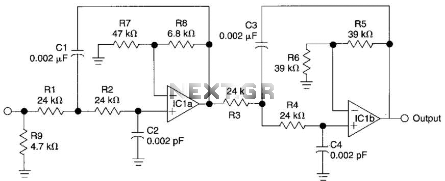
Active Fourth-Order Low-Pass Filter Circuit
This circuit is a fourth-order low-pass filter designed for operation at kilohertz frequencies. The component values for resistors R1, R2, and capacitors C1, C2, as well as resistors R3, R4 and capacitors C3, C4 can be adjusted for functionality at...

The same capacitance parameters 12dB-oct low-pass filter
In this circuit, A = 1, port = 0.5, and it features a passive vent filter without distinction. Attention is required when the circuit is dry; Q is determined by the formula Q = 1 / (3 - A). It...
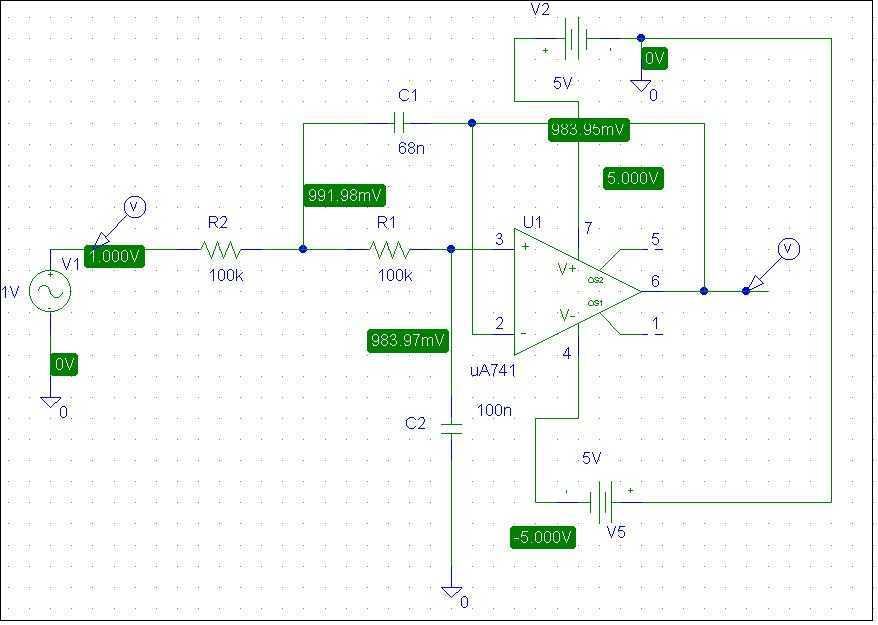
Schematic of Low-Pass Active Filter
This is a simple low pass filter that can be used at any audio circuitry. It uses the 741 opamp. More: Do not forget to use double power supply of 5 volts. You can use 2 batteries as shown in...

12dB-oct by the OP amplifiers low-pass filter
A 12dB/oct Butterworth filter circuit is designed to achieve a flat frequency response. The optimal value for the circuit's Q factor is 0.707, which ensures a flat characteristic. The feedback capacitance must be selected to maintain high capacity and reach...

8 low-pass filter MAX291 TA7504P schematic
The circuit depicted in Figure 8 is a low-pass filter utilizing an eight-stage switched-capacitor configuration. The cutoff frequency of the circuit can be adjusted, with a clock frequency that can be modified to 1/100 of the original frequency. A clock...

Low-pass filter
This circuit is useful where fast signal acquisition and high precision are required, such as in electronic scales. The filter's time constant is determined by the 2-ohm resistor and the 1 µF capacitor until comparator No. 1 activates. After this...

the designs of three phases SPWM variable frequency power supply of DSP
The variable frequency power supply is a crucial component of the power system, as its characteristics significantly impact the security and reliability of the overall system. The modern variable frequency power supply is characterized by low power consumption and high...

Common low-pass filter circuit b
A common low-pass filter circuit is illustrated. Figures (a) to (c) demonstrate its ability to suppress high-frequency interference, while Figure (b) shows a varistor that can absorb lightning surge voltage. Figure (d) indicates the circuit's capability to suppress low interference,...

Cheap DSP Experiments
This project is an experiment of the Digital Signal Processing with a cheap microcontroller instead of an ordinary digital signal processor. Recent 8 bit microcontrollers have sufficient processing performance so that they can be used for simple audio signal processing....