


Hi-Low Logic Digital tester
#logic tester
#7-segment display
#TTL
#74LS00
#NAND gate
#transistors
#digital signal
#high-low logic
#open input

Description: This tester, the logic level digital signals indicate on a 7-segment display. The display shows an H as the input signal is high. When the signal is low, the display shows an L on. If the input is open, the display shows N. The circuit consists of a TTL NAND IC type 74LS00 and three transistors. The NAND gates ensure that the right segments of the display can be controlled.
The circuit operates by utilizing a 7-segment LED display configured as a common cathode, which allows each segment to be illuminated by applying a high signal to the appropriate segment pin. The logic level tester interprets digital input signals and displays corresponding values on the 7-segment display. When the input signal is high (logic level '1'), the display shows an 'H'. Conversely, when the input signal is low (logic level '0'), the display shows an 'L'. In cases where the input is not connected, the display indicates 'N' for open.
The core of the circuit relies on a TTL NAND gate integrated circuit (74LS00), which contains four 2-input NAND gates. These gates are used to process the input signal and determine which segments of the display should be activated. The transistors in the circuit serve as switches, allowing the control signals from the NAND gates to drive the segments of the display without exceeding the current ratings of the logic gates.
Resistors R1, R2, R5, and R6, each with a value of 10 kOhm, are used for biasing and current limiting, ensuring that the transistors operate within safe limits. Resistor R3, valued at 47 kOhm, may be used for pull-down purposes or to set the base current for one of the transistors. Resistor R4, at 8.2 kOhm, is likely utilized to limit the current to one of the segments of the display. Resistors R7, at 4.7 kOhm, and R8-R12, each at 330 Ohm, are employed to control the current through the segments of the display, ensuring they illuminate correctly without damage.
In summary, this circuit effectively demonstrates the logic levels of digital signals using a 7-segment display, powered by a TTL NAND IC and controlled by transistors, with carefully selected resistor values to manage current and voltage levels throughout the system.This tester, the logic level digital signals indicate on a 7-segment display. The display shows an H as the input signal is high. When the signal is low, the display shows an L on. If the input is open, the display shows N. The circuit consists of a TTL NAND IC type 74LS00 and three transistors. The NAND gates ensure that the right segments of the display can be controlled. The display is of the type CC (common cathode ie common cathode). R1, R2 = 10 kOhm R3 = 47 kOhm R4 = 8.2 kOhm R5, R6 = 10 kOhm R7 = 4.7 kOhm R8-R12 = 330 ? LD1 = 7 segment LED display (common cathode) IC1 = IC TTL 74LS00
The circuit operates by utilizing a 7-segment LED display configured as a common cathode, which allows each segment to be illuminated by applying a high signal to the appropriate segment pin. The logic level tester interprets digital input signals and displays corresponding values on the 7-segment display. When the input signal is high (logic level '1'), the display shows an 'H'. Conversely, when the input signal is low (logic level '0'), the display shows an 'L'. In cases where the input is not connected, the display indicates 'N' for open.
The core of the circuit relies on a TTL NAND gate integrated circuit (74LS00), which contains four 2-input NAND gates. These gates are used to process the input signal and determine which segments of the display should be activated. The transistors in the circuit serve as switches, allowing the control signals from the NAND gates to drive the segments of the display without exceeding the current ratings of the logic gates.
Resistors R1, R2, R5, and R6, each with a value of 10 kOhm, are used for biasing and current limiting, ensuring that the transistors operate within safe limits. Resistor R3, valued at 47 kOhm, may be used for pull-down purposes or to set the base current for one of the transistors. Resistor R4, at 8.2 kOhm, is likely utilized to limit the current to one of the segments of the display. Resistors R7, at 4.7 kOhm, and R8-R12, each at 330 Ohm, are employed to control the current through the segments of the display, ensuring they illuminate correctly without damage.
In summary, this circuit effectively demonstrates the logic levels of digital signals using a 7-segment display, powered by a TTL NAND IC and controlled by transistors, with carefully selected resistor values to manage current and voltage levels throughout the system.This tester, the logic level digital signals indicate on a 7-segment display. The display shows an H as the input signal is high. When the signal is low, the display shows an L on. If the input is open, the display shows N. The circuit consists of a TTL NAND IC type 74LS00 and three transistors. The NAND gates ensure that the right segments of the display can be controlled. The display is of the type CC (common cathode ie common cathode). R1, R2 = 10 kOhm R3 = 47 kOhm R4 = 8.2 kOhm R5, R6 = 10 kOhm R7 = 4.7 kOhm R8-R12 = 330 ? LD1 = 7 segment LED display (common cathode) IC1 = IC TTL 74LS00

Audible-logic-tester
This tester provides an audible indication of the logic level of the signal presented to its input. A logic high is indicated by a high tone, a logic low is indicated by a low tone, and oscillation is indicated by...

Adjustable TTL clock
The symmetry of the square-wave output is maintained by connecting the right side of resistor R2 through resistor R3 to the output of the third amplifier stage. This configuration alters the charging current to the capacitors in proportion to the...

7-segment displays tutorial LEDs sample circuits
A brief history: Like many tutorials, this one begins with a historical overview. However, it must be noted that there is limited background information available regarding the development of 7-segment displays.
7-segment displays are widely used electronic components that provide...
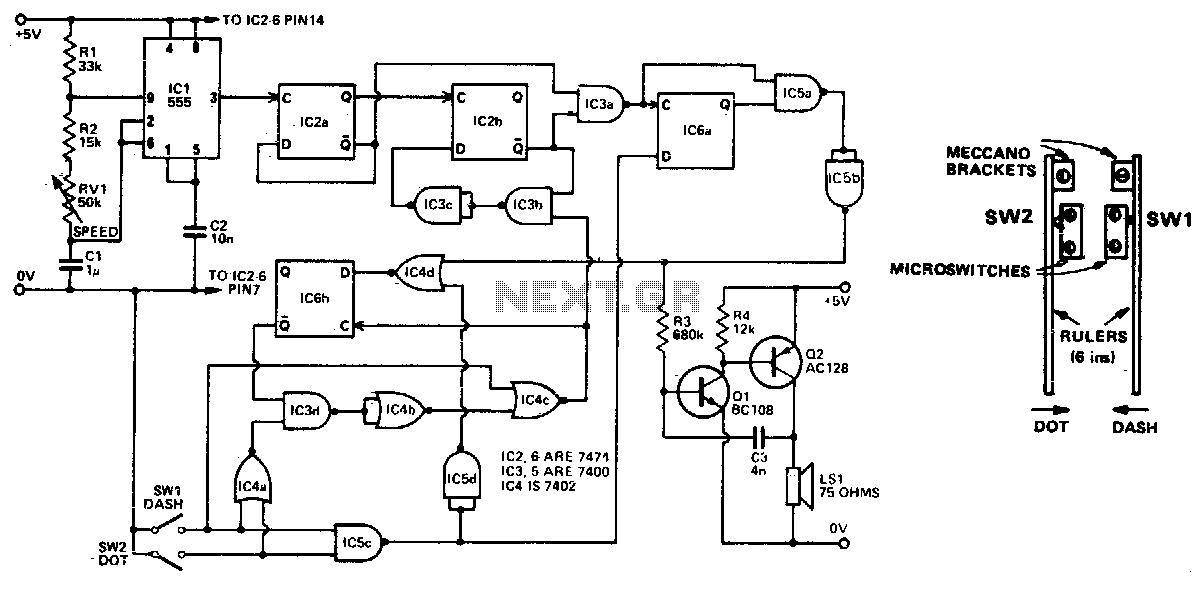
Automatic ttl morse-code keyer
Automatically generated dits and dahs are produced over a speed range of 11 to 39 wpm. The upper limit can be raised by decreasing R2. SW1 and SW2 can be a "homebrew" paddle operated key.
The described circuit is designed to...

Logic Tester
The circuit consists of two comparators that operate with different reference voltages supplied by separate potential dividers. Divider R3/R4/R5 provides a voltage of approximately 40% of the supply voltage (Ucc) to pin 6 of IC1B and about 16% of Ucc...
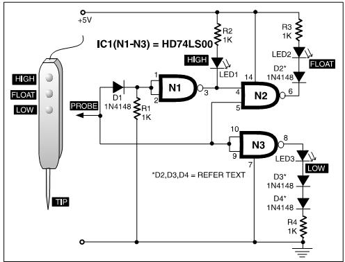
TTL Three - State Logic Probe PCB
A TTL logic probe is an essential tool for troubleshooting digital circuits. Various methods can be utilized to design a logic probe. The most common designs incorporate operational amplifiers, logic gates (OR, NOT, XOR), and transistors. The circuit described here...
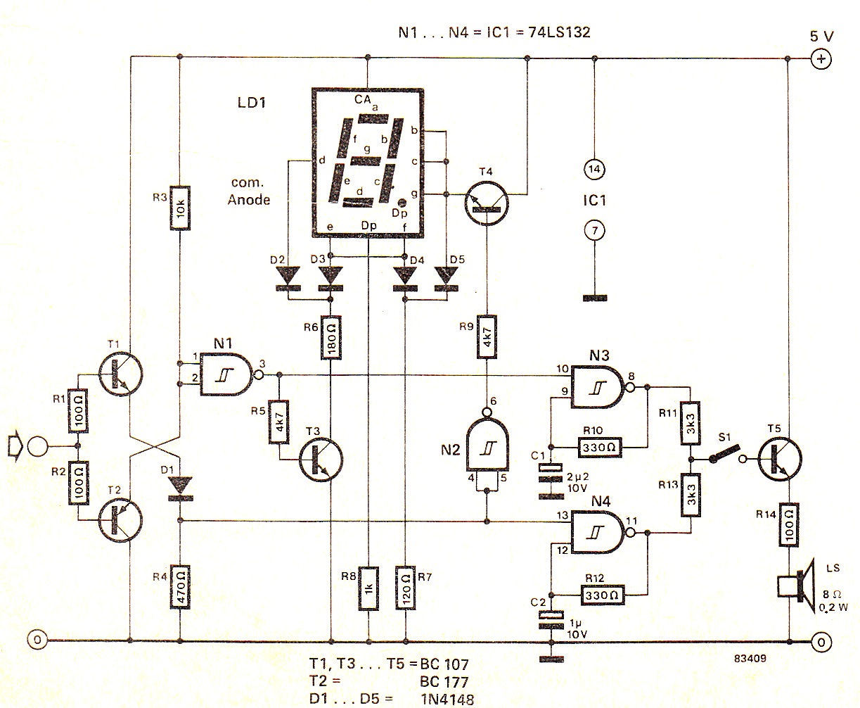
Digital High/Low Logic Tester Circuit diagram
When the input signal is at logic high (1), the display indicates `H`, and the loudspeaker emits a note that is one octave higher than the low tone. The operation of the circuit can be observed in the circuit diagram...

Curtain Control Circuit
This hybrid circuit uses a mixture of transistors, an IC and a relay and is used to automatically open or close a pair of curtains. Using switch S3 also allows manual control, allowing for curtains to be left only partially...

Switch-debouncer
The TTL inverter 74LS14 features an internal 16-kohm pull-up resistor that ensures the gate input is pulled high when the switch is open. Upon closing the switch, a 4.7uF capacitor discharges at the initial contact. If the switch contacts bounce...