


High Speed Logic Astable Multivibrator (MC74HC04)
#MC74HC04
#CMOS
#Hex Inverter
#astable multivibrator
#high speed logic
#digital oscillator
#logic gates
#pulse generator

Description: The MC74HC04 IC is a low cost CMOS Hex Inverter. I used this type mainly because, it is what I have, although you can use LS type but, with a little modification or exemptions. More: For 'HC' type: Always connect unused inputs to an appropriate voltage level (e.g. GND, or VCC), unused outputs can be left open. For 'LS' type: You can leave unused inputs open as well as unused outputs. The figure below is the schematic layout for the circuit. The circuit makes use of passive components R1, R2 and capacitor C to make the oscillation. LED1 serves as the output indicator for the High to Low transition of the circuit. PARTS ----------------------------- IC1 = MC74HC04 (1) R1 = 390kΩ (1) R2 = 680kΩ (1) R3 = 330Ω (1) C = 10uF/16V tantalum/electrolytic (1) LED1 = 5mm LED Diode any color (1 each) 9V Battery, 9V Battery Clip (1 each) * All resistors are 1/4W 5% tol. carbon composition type unless specified.
The MC74HC04 is a hex inverter, which means it contains six independent inverter gates. Each gate takes a single input signal and produces the inverse output. This IC is particularly suitable for low-cost applications and operates at a wide voltage range, making it versatile for various electronic designs. The choice of the 'HC' series is advantageous due to its high-speed performance and low power consumption compared to traditional TTL logic.
In the described circuit, the MC74HC04 is configured to create a simple oscillator. The resistors R1 and R2, along with the capacitor C, form a timing network that dictates the frequency of oscillation. The values of R1 (390kΩ) and R2 (680kΩ) are chosen to provide a suitable charge and discharge path for the capacitor C (10µF), allowing it to oscillate between high and low states.
LED1 serves as a visual indicator of the output state. When the output transitions from high to low, the LED will illuminate, providing a clear indication of the circuit's operation. The use of a 9V battery as the power source ensures that the circuit operates reliably across its components, while the 9V battery clip facilitates easy connections.
It is crucial to note that for the 'HC' type of the MC74HC04, any unused inputs must be connected to a defined logic level, either GND or VCC, to prevent floating inputs that could lead to unpredictable behavior. In contrast, the 'LS' type allows unused inputs to be left open, but this design choice may affect the performance and stability of the circuit.
The specified components, including resistors and the LED, should adhere to the stated tolerances and power ratings. All resistors are 1/4W with a tolerance of 5%, ensuring they can handle the required power without overheating. The choice of tantalum or electrolytic for the capacitor is important to maintain the stability of the oscillation frequency, as these types offer low equivalent series resistance (ESR) and good frequency response.
Overall, this circuit represents a straightforward implementation of a hex inverter in an oscillator configuration, demonstrating the fundamental principles of digital logic and timing circuits.The MC74HC04 IC is a low cost CMOS Hex Inverter. I used this type mainly because, it is what I have, although you can use LS type but, with a little modification or exemptions.. For 'HC' type: Always connect unused inputs to an appropriate voltage level (e.g. GND, or VCC), unused outputs can be left open. For 'LS' type: You can leave unused inputs open as well as unused outputs. The figure below is the schematic layout for the circuit. The circuit makes use of passive components R1, R2 and capacitor C to make the oscillation. LED1 serves as the output indicator for the High to Low transition of the circuit. PARTS ----------------------------- IC1 = MC74HC04 (1) R1 = 390kΩ (1) R2 = 680kΩ (1) R3 = 330Ω (1) C = 10uF/16V tantalum/electrolytic (1) LED1 = 5mm LED Diode any color (1 each) 9V Battery, 9V Battery Clip (1 each) * All resistors are 1/4W 5% tol. carbon composition type unless specified.
The MC74HC04 is a hex inverter, which means it contains six independent inverter gates. Each gate takes a single input signal and produces the inverse output. This IC is particularly suitable for low-cost applications and operates at a wide voltage range, making it versatile for various electronic designs. The choice of the 'HC' series is advantageous due to its high-speed performance and low power consumption compared to traditional TTL logic.
In the described circuit, the MC74HC04 is configured to create a simple oscillator. The resistors R1 and R2, along with the capacitor C, form a timing network that dictates the frequency of oscillation. The values of R1 (390kΩ) and R2 (680kΩ) are chosen to provide a suitable charge and discharge path for the capacitor C (10µF), allowing it to oscillate between high and low states.
LED1 serves as a visual indicator of the output state. When the output transitions from high to low, the LED will illuminate, providing a clear indication of the circuit's operation. The use of a 9V battery as the power source ensures that the circuit operates reliably across its components, while the 9V battery clip facilitates easy connections.
It is crucial to note that for the 'HC' type of the MC74HC04, any unused inputs must be connected to a defined logic level, either GND or VCC, to prevent floating inputs that could lead to unpredictable behavior. In contrast, the 'LS' type allows unused inputs to be left open, but this design choice may affect the performance and stability of the circuit.
The specified components, including resistors and the LED, should adhere to the stated tolerances and power ratings. All resistors are 1/4W with a tolerance of 5%, ensuring they can handle the required power without overheating. The choice of tantalum or electrolytic for the capacitor is important to maintain the stability of the oscillation frequency, as these types offer low equivalent series resistance (ESR) and good frequency response.
Overall, this circuit represents a straightforward implementation of a hex inverter in an oscillator configuration, demonstrating the fundamental principles of digital logic and timing circuits.The MC74HC04 IC is a low cost CMOS Hex Inverter. I used this type mainly because, it is what I have, although you can use LS type but, with a little modification or exemptions.. For 'HC' type: Always connect unused inputs to an appropriate voltage level (e.g. GND, or VCC), unused outputs can be left open. For 'LS' type: You can leave unused inputs open as well as unused outputs. The figure below is the schematic layout for the circuit. The circuit makes use of passive components R1, R2 and capacitor C to make the oscillation. LED1 serves as the output indicator for the High to Low transition of the circuit. PARTS ----------------------------- IC1 = MC74HC04 (1) R1 = 390kΩ (1) R2 = 680kΩ (1) R3 = 330Ω (1) C = 10uF/16V tantalum/electrolytic (1) LED1 = 5mm LED Diode any color (1 each) 9V Battery, 9V Battery Clip (1 each) * All resistors are 1/4W 5% tol. carbon composition type unless specified.

A single pulse signal generating circuit
A single pulse signal generating circuit is designed to produce a one-shot pulse output. This circuit can be utilized in applications requiring a digital reset signal or to halt a signal. It operates as a non-synchronous differential circuit.
The single pulse...

Constitute a CMOS circuit time adjustment of a spot welder
This document outlines a CMOS circuit designed for time adjustment in a spot welder. The circuit allows for the selection of a number of cycles, ranging from 1 to 99, with practical applications typically using around 10 cycles. The schematic...

Digital Clock Circuit-CMOS 4047
This circuit generates a digital square wave that can be displayed directly or utilized to drive additional circuits. It employs the CMOS 4047 Low-Power Monostable/Astable Multivibrator, as referenced in Tom Duncan's "Adventures with Digital Electronics" book, to control a CMOS...
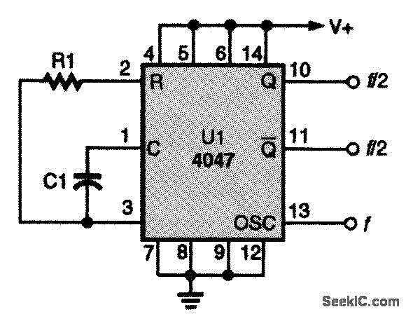
CD4047 CMOS OSCILLATOR
This CMOS square-wave oscillator utilizes the 4047 multivibrator circuit, suitable for both monostable (one-shot) and astable applications. In the provided configuration, the 4047 operates as an astable multivibrator. The circuit features three outputs from the 4047, with the first being...

Electronic Switch ON-OFF
Here we have three choices, with which we can make electronic switches that use our touch or pressing (push button). We thus exploit the very big resistance of entry, that present the gates CMOS. In the fig.1 we have two...

Slide Projector Auto Advance
A 4001 CMOS Quad NOR gate is configured as an astable multivibrator, which drives a simple differentiator and relay driver. Depending on the setting of S2, a delay of 5 to 30 seconds is generated. S2 and R1 through R6...

CMOS Toggle Flip Flop Using Laser Pointer
The circuit described operates similarly to a previous design but utilizes a laser pointer to activate the relay instead of a push button. An IR photo transistor (model Q1, Radio Shack 276-145A or equivalent) is connected to the set input...

Pulse DemodulatorCircuit
The Pulse Demodulator, as illustrated in the accompanying image, consists of a CMOS Hex Inverter. This circuit is capable of performing envelope detection on amplitude pulses.
The Pulse Demodulator utilizing a CMOS Hex Inverter is designed to extract the envelope of...

Signal injectoh-tracer
The injector is a CMOS oscillator with a period approximately equal to 1 x Cl x R2 seconds. The values are provided for 1 kHz operation. Resistors R3 and R4 divide the output to 1 V. While the oscillator operates...