


Logic Pulser Circuit

Description: The logic pulser generates pulses at 500 Hz or 0.5 Hz. When the pulser's tip connects to an input that is already being driven high or low, the pulser senses the logic state and automatically pulses the input briefly to the opposite state.
The logic pulser is a versatile electronic component designed to produce precise pulse signals at specified frequencies, namely 500 Hz and 0.5 Hz. This device is particularly useful in digital circuits where it is necessary to toggle the state of an input signal. The operation of the logic pulser is predicated on its ability to detect the current logic level of the connected input.
When the tip of the pulser is connected to an input that is already being driven either high (logic level '1') or low (logic level '0'), the pulser employs a sensing mechanism to determine the existing state of the signal. Upon detection of the current logic level, the pulser generates a pulse that briefly transitions the input to the opposite state. For instance, if the input is high, the pulser will output a low pulse, and conversely, if the input is low, it will output a high pulse.
This functionality is crucial in various applications, including digital signal processing, testing, and debugging of electronic circuits. The ability to generate a controlled pulse that can invert the state of a signal allows for effective manipulation of logic levels in a circuit, thereby facilitating the development and testing of digital systems.
The design of the logic pulser typically includes a timing circuit to regulate the frequency of the output pulses, a detection circuit to sense the input state, and a driver circuit to produce the necessary output signal. The integration of these components ensures reliable operation and precise timing, making the logic pulser an essential tool in the arsenal of electronic engineers and technicians. The logic pulser generates pulses at 500 Hz or 0.5 Hz. When the pulser`s.tip connects to an input that is already being driven high or low, the pulser senses thelogic state and automatically pulses the input briefly to the opposite state.
The logic pulser is a versatile electronic component designed to produce precise pulse signals at specified frequencies, namely 500 Hz and 0.5 Hz. This device is particularly useful in digital circuits where it is necessary to toggle the state of an input signal. The operation of the logic pulser is predicated on its ability to detect the current logic level of the connected input.
When the tip of the pulser is connected to an input that is already being driven either high (logic level '1') or low (logic level '0'), the pulser employs a sensing mechanism to determine the existing state of the signal. Upon detection of the current logic level, the pulser generates a pulse that briefly transitions the input to the opposite state. For instance, if the input is high, the pulser will output a low pulse, and conversely, if the input is low, it will output a high pulse.
This functionality is crucial in various applications, including digital signal processing, testing, and debugging of electronic circuits. The ability to generate a controlled pulse that can invert the state of a signal allows for effective manipulation of logic levels in a circuit, thereby facilitating the development and testing of digital systems.
The design of the logic pulser typically includes a timing circuit to regulate the frequency of the output pulses, a detection circuit to sense the input state, and a driver circuit to produce the necessary output signal. The integration of these components ensures reliable operation and precise timing, making the logic pulser an essential tool in the arsenal of electronic engineers and technicians. The logic pulser generates pulses at 500 Hz or 0.5 Hz. When the pulser`s.tip connects to an input that is already being driven high or low, the pulser senses thelogic state and automatically pulses the input briefly to the opposite state.

Switch-debouncer
The TTL inverter 74LS14 features an internal 16-kohm pull-up resistor that ensures the gate input is pulled high when the switch is open. Upon closing the switch, a 4.7uF capacitor discharges at the initial contact. If the switch contacts bounce...

Fast Low Duty-Cycle Pulse Oscillator
This simple and symmetrical free-running generator has a 50-ohm output impedance, a pulse width of 100 ns, and complementary outputs that swing from ground to the power supply voltage. It operates within a power supply range of less than 1...

Pulse Signal Generator
The volt-ampere characteristics of a tunnel diode exhibit an S-shaped curve. The peak current point, referred to as point P, represents the maximum current, while the valley point, denoted as point V, indicates the minimum current. Key parameters of the...

Ttl logic tester
Gates G1 and G2, along with resistors R1 and R2, create a straightforward voltage monitor with a trip point set at 1 volt. Gate G3 functions as an inverter. The display section of the tester features a common anode alphanumeric...

Sine- And Square-Wave Ttl Oscillator
A TTL oscillator utilizing a Quad NAND Gate can operate with fundamental crystals ranging from 1 to 10 MHz. The sine wave output is derived directly from the crystal, which functions as its own filter, producing a relatively clean sine...

Adjustable pulse generator circuit
An adjustable pulse generator circuit is presented, which produces a periodic signal with independently adjustable pulse widths. The electrical path allows for modifications to the signal period through the adjustment of RP1. Additionally, RP2 can be altered to change the...
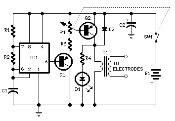
Muscular Bio-Stimulator
IC1 generates 150 µSec pulses at approximately 80Hz frequency. Q1 functions as a buffer, while Q2 inverts the pulse polarity and drives the transformer. The output pulse amplitude is adjusted by P1 and is visually indicated by the brightness of...
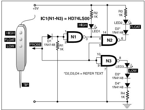
TTL Three - State Logic Probe PCB
A TTL logic probe is an essential tool for troubleshooting digital circuits. Various methods can be utilized to design a logic probe. The most common designs incorporate operational amplifiers, logic gates (OR, NOT, XOR), and transistors. The circuit described here...

Logic-pulser
The pulser generates pulses at a user-selected frequency of 0.5 or 500 Hz, with a pulse width of about 5 ms. If the input to be pulsed is already being driven high or low by another output, the pulser automatically...