


Low-Cost Dual Digital Dice
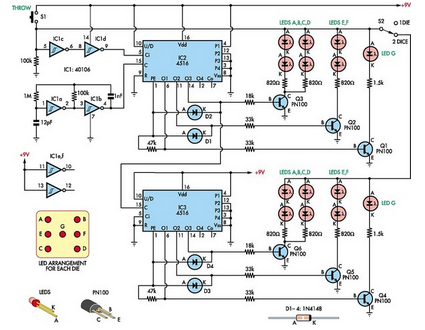
Description: This simple dual digital dice is based on three low-cost integrated circuits (ICs), a few transistors, and several light-emitting diodes (LEDs). IC1a and IC1b function as oscillators with a specific frequency.
The dual digital dice circuit utilizes three low-cost integrated circuits to create a simple yet effective random number generator. The primary components include two oscillators (IC1a and IC1b), which generate clock pulses at a defined frequency. These oscillators are typically configured using a 555 timer IC or similar, producing a square wave output that drives the subsequent logic in the circuit.
Transistors are employed to amplify signals and control the operation of the LEDs, which visually represent the dice rolls. The LEDs are arranged in a manner that allows them to light up in patterns corresponding to the numbers displayed on traditional dice. The circuit can be designed to show numbers from one to six for each die, with the output being triggered by a push-button switch or a similar input mechanism.
The circuit's operation begins when the user activates the switch, causing the oscillators to start generating clock pulses. These pulses are fed into a binary counter or a similar digital logic component, which counts the pulses and determines the output state. As the counter increments, it activates the appropriate LEDs to reflect the current count, simulating the roll of two dice.
To enhance the user experience, additional features can be integrated, such as sound effects using a small speaker or buzzer that activates with each roll, or a reset function that allows the user to clear the displayed numbers. The design can be compact, making it suitable for portable applications or as a fun addition to board games. Overall, this dual digital dice circuit combines simplicity and functionality, making it an excellent project for electronics enthusiasts.This simple dual digital dice is based on three low-cost ICs, a few transistors and a handful of LEDs. IC1a & IC1b operate as an oscillator with a frequen..
The dual digital dice circuit utilizes three low-cost integrated circuits to create a simple yet effective random number generator. The primary components include two oscillators (IC1a and IC1b), which generate clock pulses at a defined frequency. These oscillators are typically configured using a 555 timer IC or similar, producing a square wave output that drives the subsequent logic in the circuit.
Transistors are employed to amplify signals and control the operation of the LEDs, which visually represent the dice rolls. The LEDs are arranged in a manner that allows them to light up in patterns corresponding to the numbers displayed on traditional dice. The circuit can be designed to show numbers from one to six for each die, with the output being triggered by a push-button switch or a similar input mechanism.
The circuit's operation begins when the user activates the switch, causing the oscillators to start generating clock pulses. These pulses are fed into a binary counter or a similar digital logic component, which counts the pulses and determines the output state. As the counter increments, it activates the appropriate LEDs to reflect the current count, simulating the roll of two dice.
To enhance the user experience, additional features can be integrated, such as sound effects using a small speaker or buzzer that activates with each roll, or a reset function that allows the user to clear the displayed numbers. The design can be compact, making it suitable for portable applications or as a fun addition to board games. Overall, this dual digital dice circuit combines simplicity and functionality, making it an excellent project for electronics enthusiasts.This simple dual digital dice is based on three low-cost ICs, a few transistors and a handful of LEDs. IC1a & IC1b operate as an oscillator with a frequen..

Quick Counter For Young Children
This circuit is a toy designed to help young children learn to count. Power is activated by switch S1, followed by closing switch S2, which causes nine LEDs to flash slowly. When S2 is opened, the LEDs turn off. Pressing...

Electronics Projects Circuits
Over 1400 top electronics projects and electronic circuits with photos, datasheets, and easy-to-read schematics, along with explanations of how they work and how to build them.
The collection comprises a vast array of electronics projects suitable for enthusiasts and professionals alike....

The Metal Detector Circuit
This design has not been referred to as a GOLD detector, as that term is reserved for more complex devices capable of distinguishing gold from other metals. There is a significant difference between detecting gold and ordinary metals, known as...

Metal detector circuit diagram 1
The metal detector circuit includes a fixed frequency oscillator, mixer, detector, detection oscillator, and power amplifier circuit. The fixed frequency oscillator circuit is composed of a ceramic filter (ZC), transistor (V1), resistors (R1 to R4), capacitor (C2), and other components....

Acousto-optic detector circuit to measure the crystal
The circuit consists of a capacitance three-point oscillator, an isolation level, a voltage doubler rectifier circuit, a stereo sound circuit, and a flash display circuit. It can detect the quality of a crystal; a good crystal will emit a "Didi"...

Color Mirror Screw Project
This project requires a 1200 RPM synchronous motor and a light source composed of a vertically arranged row of LEDs, positioned approximately 6 inches from the screw. The intention is to enclose all components within a clear plastic cabinet for...
Last-cycle-completing-gated-oscillator
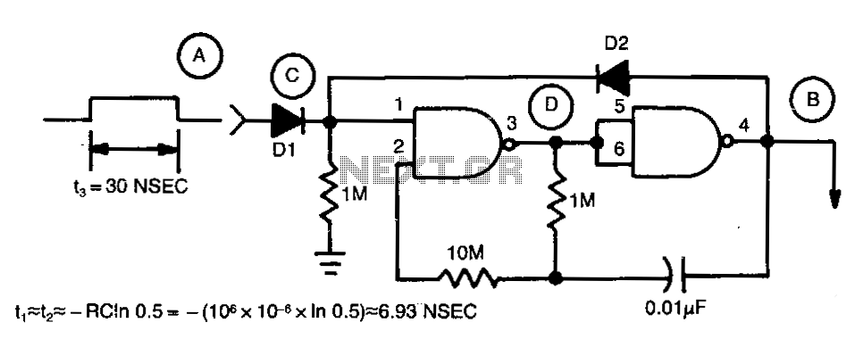
Regenerative feedback at capacitor C allows the oscillator to complete its timing cycle instead of shutting off immediately. The integrated circuit (IC) used was a CD4011AE, although an equivalent IC will also function.
The described circuit utilizes regenerative feedback to enhance...

Metal detector circuit diagram 5
The metal detector circuit comprises an oscillator and a sound-light alarm circuit. The oscillator circuit includes an inductor (L), a capacitor (C1), a sensor switch integrated circuit (IC1) that integrates the oscillator, detector, comparator circuit, and peripheral components. The sound-light...

inverter circuit diagram
A common topology for DC-AC power converter circuits employs a pair of transistors to switch DC current through the center-tapped winding of a step-up transformer. Examine the check plot images from a PCB drafting program for a control board based...