


MULTIPLEXED CLOCK DlSPLAY
#TTL counters
#multiplexed display
#LED readout
#flip-flop
#shift register
#clock display
#60-Hz line
#gate logic
#timekeeping

Description: A multiplexed display suitable for LED readouts is provided by a circuit that uses TTL counters to count a 60-Hz line. When the count reaches the hour mark, flip-flop M is set on every cycle. Gate G3 then detects when the time reaches 13:00, and clears the shift register. The carry flip-flop remains set, allowing a '1' to be loaded into the hours digit to facilitate the transition from 12:59:59 to 1:00.
The circuit described is a digital clock display system utilizing multiplexing techniques to manage LED output effectively. The core of the design is based on TTL (Transistor-Transistor Logic) counters, which are employed to count pulses generated by a stable 60-Hz oscillator. This frequency corresponds to the standard timing for seconds in a minute, ensuring accurate timekeeping.
At the heart of the counting mechanism is a series of flip-flops, specifically designed to handle the transitions between different time states. Flip-flop M plays a crucial role by being set on every cycle once the counter reaches the designated hour mark. This flip-flop acts as a control signal that indicates the transition from one hour to the next.
Gate G3 is implemented to monitor the output of the counters. It is configured to recognize the specific condition when the count reaches 13:00 (or 1:00 PM in a 12-hour format). Upon detection of this condition, Gate G3 sends a signal to clear the contents of the shift register, effectively resetting the seconds and minutes while preparing the system for the next hour.
Additionally, the carry flip-flop is essential for ensuring that the hour digit increments correctly. When the time transitions from 12:59:59 to 1:00, the carry flip-flop remains set, which allows a binary '1' to be loaded into the hours digit. This mechanism ensures seamless transitions in the display, maintaining the integrity of the time representation.
Overall, this multiplexed display circuit is a robust solution for digital clock applications, providing accurate time display while minimizing the complexity of the circuitry through the use of TTL technology and efficient counting mechanisms.Multiplexed display suitable for LED readouts is provided by circuit using TTL counters to count 60-Hz Iine.When count reaches o`clock, flip-flop M is set on evely cycle. Gate G3 then detects when time goes to 13 o`clock, and clears shift register.Carry flip-flop remains set, so 1 is loaded into hours digit to accomplish transition from 12:59:59 to 1:0..
The circuit described is a digital clock display system utilizing multiplexing techniques to manage LED output effectively. The core of the design is based on TTL (Transistor-Transistor Logic) counters, which are employed to count pulses generated by a stable 60-Hz oscillator. This frequency corresponds to the standard timing for seconds in a minute, ensuring accurate timekeeping.
At the heart of the counting mechanism is a series of flip-flops, specifically designed to handle the transitions between different time states. Flip-flop M plays a crucial role by being set on every cycle once the counter reaches the designated hour mark. This flip-flop acts as a control signal that indicates the transition from one hour to the next.
Gate G3 is implemented to monitor the output of the counters. It is configured to recognize the specific condition when the count reaches 13:00 (or 1:00 PM in a 12-hour format). Upon detection of this condition, Gate G3 sends a signal to clear the contents of the shift register, effectively resetting the seconds and minutes while preparing the system for the next hour.
Additionally, the carry flip-flop is essential for ensuring that the hour digit increments correctly. When the time transitions from 12:59:59 to 1:00, the carry flip-flop remains set, which allows a binary '1' to be loaded into the hours digit. This mechanism ensures seamless transitions in the display, maintaining the integrity of the time representation.
Overall, this multiplexed display circuit is a robust solution for digital clock applications, providing accurate time display while minimizing the complexity of the circuitry through the use of TTL technology and efficient counting mechanisms.Multiplexed display suitable for LED readouts is provided by circuit using TTL counters to count 60-Hz Iine.When count reaches o`clock, flip-flop M is set on evely cycle. Gate G3 then detects when time goes to 13 o`clock, and clears shift register.Carry flip-flop remains set, so 1 is loaded into hours digit to accomplish transition from 12:59:59 to 1:0..

Astable Flip-flops
The astable flip-flop circuit is a versatile configuration used for creating flashers or generating square waves. A common application is an alternating LED flasher where the LEDs are connected in the emitters instead of the collectors, which is the more...

Practical flip-flop circuit
A flip-flop circuit with a memory function for pulse signals. It features two stable states: one where transistor VTi is off and VTZ is conducting, and another where VTi is conducting and VT2 is off. An external signal is sufficient...

Lights Out circuit
The design is based on the previous analysis of calculating the game in a circular shift register. While designing, it was realized that small extensions to the design would enable additional gameplay features, such as replay and manual input. The...
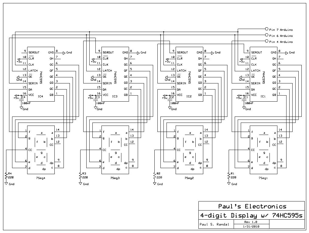
cascading shift registers to drive 7-segment displays with PC input
Four 595 shift registers are used together to drive 7-segment displays, with additional code implemented to accept input from a PC. Unlike the previous design that utilized 10-LED bar graphs, the current configuration employs 7-segment displays, which present a greater...

Shift register
The shift pulse amplitude is less than 15 volts. If a stage is off, the shift pulse will not be coupled to the next stage. If it is on, the diode will conduct and trigger the next stage. Just prior...

Flip-Flop Independent Lamp Driver
Assume first that SCR1 is on and SCR2 is off, allowing capacitor CI to be fully charged, with its LMP2 end positive. The state of the circuit can be altered by pressing switch S2. When SCR2 turns on, it capacitively...

Divide-circuit
An input signal drives both SN74 D-type flip-flops, which are positive edge-triggered devices. A low-to-high input signal transition triggers the A flip-flop, while a high-to-low input signal transition triggers the B flip-flop via the SN7404 inverter. Either flip-flop in the...

Synchronous RS flip-flop circuit structure and symbols
The asynchronous RS flip-flop mentioned earlier is not synchronized with the system clock signal. In contrast, the synchronous RS flip-flop incorporates synchronization, allowing it to operate in conjunction with the clock signal. Figure (a) illustrates the circuit configuration of the...

S/R Flip-Flop
This circuit combines the characteristics of an asynchronous S/R flip-flop and an edge-triggered JK flip-flop. It changes state on the leading edges of its inputs and ignores the levels at all other times. In operation, the outputs of both D...