


Nuar
#12-bit counter
#7 segment display
#LED
#frequency divider
#blink signal
#digital display
#logic circuit
#binary counter

Description: The counter operates at 12 bits, resulting in a division factor of 1/4096. This allows a 4 kHz signal to be displayed in approximately 500 milliseconds. A 7-segment display consists of 7 LEDs housed within a single enclosure. Each LED is shaped and positioned to form a distinct "segment," enabling the display of digits from 0 to 9 in various patterns. The segments are typically labeled from A to G. For instance, to display the number 2, segments A, B, G, E, and D are illuminated, while number 3 requires segments A, B, C, D, and G. When all seven segments are lit, the number 8 is displayed. Despite the name, most modern 7-segment displays actually contain 8 LEDs, with the additional LED used for the decimal point, commonly referred to as "H" or "DP." To minimize the pin count from 16 to 9, most 7-segment displays connect one pin from all internal LEDs to a single display pin. In "common cathode" displays, all cathodes are linked together and connected to the common cathode pin, while the anodes are connected to individual segment pins. Conversely, "common anode" displays have their anodes connected together. The TFK214 display selected for this project is a common cathode 7-segment display, with cathodes connected to pin 3 and anodes of segments A, B, C, D, E, F, G, and H connected to the remaining pins. Pin 6 is also linked to the common cathode, requiring only a single connection to the negative supply. Each segment can be lit individually, similar to any other LED. Additional digits can be added by constructing additional circuits and connecting the pin 11-6 junction of the 74LS90 and 74LS47 to pin 14 of the 74LS90 in the subsequent circuits, allowing for expansion to as many digits as desired.
The 12-bit counter configuration plays a crucial role in the operation of the 7-segment display system. The division factor of 1/4096 allows for a precise control of the frequency, enabling the user to visualize the output in a manageable timeframe of approximately 500 milliseconds. This is particularly useful in applications where timing and visual feedback are essential.
The 7-segment display is a widely utilized component in digital electronics, providing a straightforward method for displaying numerical information. Each segment's design allows for the formation of numbers through selective illumination, which is controlled by a microcontroller or a digital logic circuit. The labeling of segments A through G facilitates easy reference when designing the driving circuitry.
In typical applications, the common cathode configuration of the TFK214 display simplifies the circuit design by allowing all cathodes to be connected to ground, while the anodes can be controlled independently. This arrangement reduces the complexity of the wiring and the number of required connections to the microcontroller or logic chips.
The ability to cascade multiple displays by linking the output of one circuit to the input of another enhances the versatility of the system. By connecting the pin 11-6 junction of the 74LS90 and 74LS47 to pin 14 of the subsequent 74LS90, it is possible to create a multi-digit display system that can represent larger numerical values or perform more complex functions.
In conclusion, the design and implementation of a 12-bit counter driving a common cathode 7-segment display, such as the TFK214, provides a robust solution for numerical visualization in various electronic applications. The modular nature of the circuit allows for easy expansion, making it suitable for a range of projects, from simple digital clocks to more complex data display systems.Because it is the 12 bits, the highest rank counter is divided to 1/4096. Because it is, in the highest rank, the signal of 4KHz can be seen in the about 500-millisecond blink. A 7 segment display is manufactured encapsulating 7 LEDs inside a single case. Each LED is given a shape and position which makes it a separate "segment": lighting teo or m ore segment in different patterns, we can read all digits from 0 to 9 on the display. Segmenfs are conventionally identified with letters from A to G. The schematic diagram above shows the correspondence between segment position and the letter. For example, number 2 is obtained lighting segments A, B, G, E, D, whereas number 3 requires segments A, B, C, D, G. If all seven segments are lit then a number 8 is obtained. Despite of its name, practically all modern 7-segment displays contain 8 LEDs! This eitghth segment is required for the decimal point, and it is conventionally labelled "H" or "DP".
To reduce pin count from 16 to 9, almost all 7-segment displays connect together one pin from all of the internal LEDs bringing it to a single display pin. In the case of so called "common cathode" displays, all cathodes are connected together and to the common cathode pin, while the anodes are connected to segment pins indifdually.
The opposite for "common anode" displays. The TFK214 display we selected for this projects is a common cathode 7-segment display. The catodhes are connected to pin 3, with anodes of segments A, B, C, D, E, F, G, H to the remaining pins. Pin 6 is connected to the common cathode as well; you need to connect only one to the negative supply.
You can try to light any segment up as you do with any other LED. 2. You can add more digits by building a second (or third, or fourth, etc. ) circuit and connecting the pin 11-6 junction of the 74LS90 and 74LS47 to pin 14 of the 74LS90 in the other circuit. You can keep expanding this way to as many digits as you want.
The 12-bit counter configuration plays a crucial role in the operation of the 7-segment display system. The division factor of 1/4096 allows for a precise control of the frequency, enabling the user to visualize the output in a manageable timeframe of approximately 500 milliseconds. This is particularly useful in applications where timing and visual feedback are essential.
The 7-segment display is a widely utilized component in digital electronics, providing a straightforward method for displaying numerical information. Each segment's design allows for the formation of numbers through selective illumination, which is controlled by a microcontroller or a digital logic circuit. The labeling of segments A through G facilitates easy reference when designing the driving circuitry.
In typical applications, the common cathode configuration of the TFK214 display simplifies the circuit design by allowing all cathodes to be connected to ground, while the anodes can be controlled independently. This arrangement reduces the complexity of the wiring and the number of required connections to the microcontroller or logic chips.
The ability to cascade multiple displays by linking the output of one circuit to the input of another enhances the versatility of the system. By connecting the pin 11-6 junction of the 74LS90 and 74LS47 to pin 14 of the subsequent 74LS90, it is possible to create a multi-digit display system that can represent larger numerical values or perform more complex functions.
In conclusion, the design and implementation of a 12-bit counter driving a common cathode 7-segment display, such as the TFK214, provides a robust solution for numerical visualization in various electronic applications. The modular nature of the circuit allows for easy expansion, making it suitable for a range of projects, from simple digital clocks to more complex data display systems.Because it is the 12 bits, the highest rank counter is divided to 1/4096. Because it is, in the highest rank, the signal of 4KHz can be seen in the about 500-millisecond blink. A 7 segment display is manufactured encapsulating 7 LEDs inside a single case. Each LED is given a shape and position which makes it a separate "segment": lighting teo or m ore segment in different patterns, we can read all digits from 0 to 9 on the display. Segmenfs are conventionally identified with letters from A to G. The schematic diagram above shows the correspondence between segment position and the letter. For example, number 2 is obtained lighting segments A, B, G, E, D, whereas number 3 requires segments A, B, C, D, G. If all seven segments are lit then a number 8 is obtained. Despite of its name, practically all modern 7-segment displays contain 8 LEDs! This eitghth segment is required for the decimal point, and it is conventionally labelled "H" or "DP".
To reduce pin count from 16 to 9, almost all 7-segment displays connect together one pin from all of the internal LEDs bringing it to a single display pin. In the case of so called "common cathode" displays, all cathodes are connected together and to the common cathode pin, while the anodes are connected to segment pins indifdually.
The opposite for "common anode" displays. The TFK214 display we selected for this projects is a common cathode 7-segment display. The catodhes are connected to pin 3, with anodes of segments A, B, C, D, E, F, G, H to the remaining pins. Pin 6 is connected to the common cathode as well; you need to connect only one to the negative supply.
You can try to light any segment up as you do with any other LED. 2. You can add more digits by building a second (or third, or fourth, etc. ) circuit and connecting the pin 11-6 junction of the 74LS90 and 74LS47 to pin 14 of the 74LS90 in the other circuit. You can keep expanding this way to as many digits as you want.
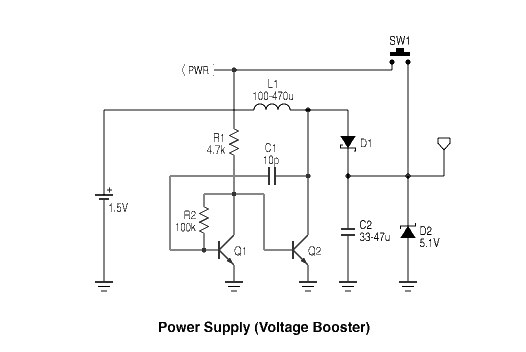
Wave Joule Thief circuit
A series of LEDs that turn on and off in a precise sequence, creating a calming and hypnotic effect. Various LED chaser, scanner, and sequencer circuits exist, utilizing discrete transistors, logic integrated circuits (ICs), or microcontrollers. However, a common limitation...

meter How to light an LED when a voltage hits a certain point
A LED is used to indicate when a DC voltage reaches 5 volts or more. The LED should be fully illuminated at 5 volts and not dim at 4.5 volts or lower. The circuit should be constructed using discrete components,...
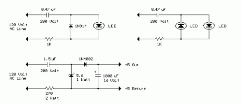
AC Line powered LEDs
The circuit below demonstrates how to power one or two LEDs from a 120-volt AC line. It utilizes a capacitor to reduce the voltage and a small resistor to limit the inrush current. As the capacitor needs to allow current...

8x8x8 LED Cube
A total of 512 functional LEDs is required for the lattice assembly. These LEDs must be stable and bright. This section outlines the process for identifying faulty LEDs among the usable ones. Often, there are defective LEDs, particularly when purchased...

simplest light with constant-current LED circuit
Here is a simple and inexpensive ($1) LED driver circuit. The circuit functions as a constant current source, ensuring that the LED maintains consistent brightness.
The LED driver circuit is designed to provide a stable current to the LED, which is...
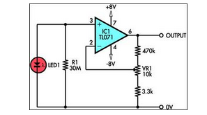
using led as a light sensor
This circuit demonstrates the utilization of a standard LED as a light sensor. It leverages the photovoltaic voltage generated across the LED when exposed to light.
The circuit operates on the principle that an LED can function as a photodiode, generating...

Led Flasher with a BC547 NPN transistor
This is a novel flasher circuit using a single driver transistor that takes its flash-rate from a flashing LED. The flasher in the photo is 3mm. An ordinary LED will not work. The flash rate cannot be altered by the...
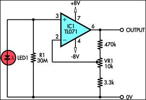
using led as a light sensor
This circuit demonstrates the use of a standard LED as a light sensor. It utilizes the photovoltaic voltage generated across the LED when exposed to light. LEDs are more cost-effective than photodiodes and feature an integrated filter, which is advantageous...

Christmas Star with LEDs
Using a PC parallel port to control external devices is a popular approach these days but I certainly couldn’t afford to tie up a PC for the few weeks leading up to Christmas just to flash a few LEDs! Not...