


Optical toggle switch with 4027
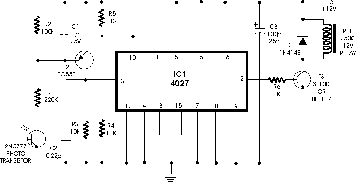
Description: Using dual flip-flop IC CD4027 employ a 555 based monostable circuit to supply input clock pulses. The circuit described here obviates this requirement. One of the two flip-flops within IC CD4027 itself acts as square wave shaper.
The circuit utilizes the dual flip-flop integrated circuit CD4027, which contains two independent flip-flops that can be configured as either RS, JK, or D types. This versatility allows for various applications, including the generation of clock pulses. In this specific application, the circuit eliminates the need for an external 555 timer by employing one of the flip-flops to generate square wave signals directly.
The configuration involves setting up one flip-flop in a toggle mode, where the output changes state with each clock pulse received. The clock pulses can be generated from the output of the flip-flop itself or from an external source, depending on the desired frequency and stability. The output from this flip-flop serves as a square wave generator, providing a continuous stream of pulses that can be used as a timing signal for other components in a larger system.
The second flip-flop can be utilized for various purposes, such as dividing the frequency of the square wave output or as a data storage element in sequential circuits. The CD4027's ability to operate over a wide voltage range (from 3V to 15V) makes it suitable for various applications in digital logic circuits.
Overall, this configuration simplifies the design by integrating the clock generation within the flip-flop IC, thereby reducing component count and enhancing reliability. The resulting circuit is efficient for applications requiring precise timing and pulse generation without the complexity of additional components like the 555 timer.Using dual flip-flop IC CD4027 employ a 555 based monostable circuit to supply input clock pulses. The circuit described here obviates this requirement. One of the two flip-flops within IC CD4027 itself acts as square wave shaper.
The circuit utilizes the dual flip-flop integrated circuit CD4027, which contains two independent flip-flops that can be configured as either RS, JK, or D types. This versatility allows for various applications, including the generation of clock pulses. In this specific application, the circuit eliminates the need for an external 555 timer by employing one of the flip-flops to generate square wave signals directly.
The configuration involves setting up one flip-flop in a toggle mode, where the output changes state with each clock pulse received. The clock pulses can be generated from the output of the flip-flop itself or from an external source, depending on the desired frequency and stability. The output from this flip-flop serves as a square wave generator, providing a continuous stream of pulses that can be used as a timing signal for other components in a larger system.
The second flip-flop can be utilized for various purposes, such as dividing the frequency of the square wave output or as a data storage element in sequential circuits. The CD4027's ability to operate over a wide voltage range (from 3V to 15V) makes it suitable for various applications in digital logic circuits.
Overall, this configuration simplifies the design by integrating the clock generation within the flip-flop IC, thereby reducing component count and enhancing reliability. The resulting circuit is efficient for applications requiring precise timing and pulse generation without the complexity of additional components like the 555 timer.Using dual flip-flop IC CD4027 employ a 555 based monostable circuit to supply input clock pulses. The circuit described here obviates this requirement. One of the two flip-flops within IC CD4027 itself acts as square wave shaper.

Light Gate With Counter Using 555 And 4033
The described circuit counts the number of interruptions of an infrared beam. This could be used to tally the number of people entering a room or to monitor how often an object, such as a ball, passes through an opening,...
Rotation Sensor Circuit Using 555 PCB
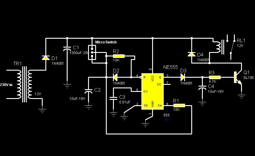
The circuit diagram illustrates a rotation sensor that activates a device, such as a motor or buzzer, when the circuit assembly is rotated. The design is based on the fundamental operation of a 555 timer.
The rotation sensor circuit utilizes a...

Mono stable with 555 and relay
The two circuits below illustrate using the 555 timer to close a relay for a predetermined amount of time by pressing a momentary N/O push button. The circuit on the left can be used for long time periods where the...

Audio Astable Multivibrator Using IC 555 Circuit
This circuit diagram illustrates the configuration of a 555 timer integrated circuit (IC) as an astable multivibrator. An astable multivibrator is a timing circuit characterized by unstable 'low' and 'high' states. Consequently, the output of an astable multivibrator continuously toggles...

Versatile Discrete Monostable Multivibrator
This is a versatile discrete monostable circuit. The circuit consists of a 2N3819 JFET and 2N3704 transistors. This monostable multivibrator circuit has an additional input to enable or inhibit the function at any time without causing an output pulse. The...

Electronic Siren
This circuit produces a sound similar to a factory siren. It makes use of a 555 timer IC used as an astable multivibrator of a center frequency of about 300Hz. The frequency is controlled by pin 5 of the IC....

Voltage Controlled Switch with 555
The old and omnipresent NE555 can be very good at something it was not meant for: driving relays or other loads up to 200 mA. The picture shows an example circuit: if the input level rises over 2/3 of the...

555 Am TransmitterCircuits
Two ICM7555 CMOS 555 timers are available, and there is an inquiry about effective AM radio transmitter circuits that utilize one or both of these timers.
The ICM7555 is a low-power CMOS version of the classic 555 timer, which can be...

pwm using 555 timer ic
The 555 integrated circuit (IC) is configured in monostable mode of operation. In this mode, the output remains LOW (0V) when there is no trigger input. When a trigger is applied through pin 2, the output switches to HIGH (Vcc)...