


Output Assign Module
#GAL
#address decoding
#VHDL
#microcontroller
#pushbutton switches
#enable signal
#digital circuit
#logic design

Description: The output assignment module utilizes a 16V8 GAL for address decoding and enable signal generation. The pin assignments for the GAL used in this module are depicted in Figure 44. The VHDL code required to generate the GALs is provided in the appendices. The status of 18 pushbutton switches must be detected by the microcontroller. Various methods exist for connecting switches to a microcontroller bus. To minimize the number of components and CPU usage, simple latches are employed to capture the status of eight switches at a time. Firmware debouncing routines will replace hardware debouncing techniques. The absence of a multiplexing scheme reduces CPU time spent reading switch values, while the firmware debouncing routines lead to a decrease in the number of components required on the board. Figure 45 illustrates the circuit designed to achieve these objectives. Three of these circuits are implemented, allowing for a total of 24 pushbutton inputs. Six of these inputs are allocated for pushbuttons in the universal user interface and cue stack sections of the control board. The output assignment module also includes several LED indicators that require control by the microcontroller. A straightforward current-sinking scheme utilizing 74LS373 octal latches is employed, similar to that of the fader module. Figure 46 presents the corresponding circuit. Additionally, the output assignment module features a pair of 7-segment LED displays, which are also controlled by the microcontroller. Although it would have been feasible to drive the displays in a manner akin to the bare LEDs on the same board, this approach was avoided due to the extra bus ports required. Instead, BCD-to-7-segment decoders are utilized, with their inputs driven from a 74LS373 latch. Figure 47 displays the circuit used to operate the 7-segment displays. Notably, the ripple zero-blanking feature of the 74LS247 BCD-to-7-segment chips is employed, which will blank both displays when a double-zero is shown and will blank the leftmost display when its value is zero.
The output assignment module is a critical component in managing user inputs and visual feedback in electronic systems. The utilization of a 16V8 GAL for address decoding ensures efficient signal routing and reduces the complexity of the overall design. The GAL's pin configuration, as shown in Figure 44, outlines the connections necessary for proper functionality, facilitating seamless integration with the microcontroller.
For switch detection, the implementation of simple latches allows the microcontroller to efficiently monitor the status of 18 pushbutton switches. By latching the status of eight switches at a time, the design minimizes the number of components while optimizing CPU performance. Firmware debouncing routines enhance the reliability of switch inputs without the need for additional hardware, thus streamlining the circuit design. The architecture depicted in Figure 45 showcases the arrangement of these circuits, emphasizing the modularity and scalability of the input handling system.
The output assignment module also incorporates LED indicators that provide visual feedback to the user. The use of 74LS373 octal latches for controlling these indicators allows for a clean and efficient current-sinking scheme, as represented in Figure 46. This design choice parallels the fader module, ensuring consistency across the control board.
Furthermore, the inclusion of 7-segment LED displays enhances the user interface by providing clear numerical readouts. The decision to utilize BCD-to-7-segment decoders, driven by a 74LS373 latch, reflects a thoughtful consideration of bus port limitations while maintaining display functionality. The circuit illustrated in Figure 47 demonstrates the effective use of the ripple zero-blanking feature of the 74LS247 chips, which optimizes display readability by eliminating unnecessary visual clutter when displaying zero values.
Overall, the output assignment module exemplifies a well-engineered solution for managing user inputs and outputs in electronic systems, combining efficient design principles with practical implementation strategies.The output assign modules uses a 16V8 GAL for address decoding and enable signal generation. Figure 44 shows the pin assignments for the GAL used in the output assign module. The VHDL code used to generate the GALs is included in the appendices, on page The status of 18 pushbutton switches need to be sensed by the microcontroller. Many methods exi st for connecting switches to a microcontroller bus. To keep parts count and CPU use down, simple latches are used to latch the status of eight switches at a time. Firmware debouncing routines shall take the place of hardware debouncing techniques. The lack of a multiplexing scheme means less CPU time is wasted in reading in the values of the switches, while the firmware debouncing routines mean fewer components are used on the board.
Figure 45 shows the circuit used to achieve these goals. Three of these circuits are present, providing a total of 24 pushbutton inputs. Six of these inputs are used for pushbuttons in the universal user interface and cue stack sections of the control board. Figure 45: Output assign module, momentary pushbutton decoding schematic. The output assign module uses three of these circuits, for a total decoding capability of 18 on-board and 6 off-board buttons.
The output assign module contains several LED indicators that need to be controlled by the microcontroller. A simple current-sinking scheme involving 74LS373 octal latches is used, identical to that of the fader module.
Figure 46 shows the circuit. The output assign module contains a pair of 7-segment LED displays, controlled by the microcontroller. While it certainly would have been possible to drive the displays in a similar fashion to the bare LEDs present on the same board, this was decided against due to the extra bus ports needed.
Instead, BCD-to-7-segment decoders were used, with their inputs driven from a 74LS373 latch. Figure 47 shows the circuit used to drive the 7-segment displays. Note the use of the ripple zero-blanking feature of the 74LS247 BCD-to-7-segment chips. This feature will blank both displays when the a double-zero is displayed, and blank the leftmost display when its value is zero.
The output assignment module is a critical component in managing user inputs and visual feedback in electronic systems. The utilization of a 16V8 GAL for address decoding ensures efficient signal routing and reduces the complexity of the overall design. The GAL's pin configuration, as shown in Figure 44, outlines the connections necessary for proper functionality, facilitating seamless integration with the microcontroller.
For switch detection, the implementation of simple latches allows the microcontroller to efficiently monitor the status of 18 pushbutton switches. By latching the status of eight switches at a time, the design minimizes the number of components while optimizing CPU performance. Firmware debouncing routines enhance the reliability of switch inputs without the need for additional hardware, thus streamlining the circuit design. The architecture depicted in Figure 45 showcases the arrangement of these circuits, emphasizing the modularity and scalability of the input handling system.
The output assignment module also incorporates LED indicators that provide visual feedback to the user. The use of 74LS373 octal latches for controlling these indicators allows for a clean and efficient current-sinking scheme, as represented in Figure 46. This design choice parallels the fader module, ensuring consistency across the control board.
Furthermore, the inclusion of 7-segment LED displays enhances the user interface by providing clear numerical readouts. The decision to utilize BCD-to-7-segment decoders, driven by a 74LS373 latch, reflects a thoughtful consideration of bus port limitations while maintaining display functionality. The circuit illustrated in Figure 47 demonstrates the effective use of the ripple zero-blanking feature of the 74LS247 chips, which optimizes display readability by eliminating unnecessary visual clutter when displaying zero values.
Overall, the output assignment module exemplifies a well-engineered solution for managing user inputs and outputs in electronic systems, combining efficient design principles with practical implementation strategies.The output assign modules uses a 16V8 GAL for address decoding and enable signal generation. Figure 44 shows the pin assignments for the GAL used in the output assign module. The VHDL code used to generate the GALs is included in the appendices, on page The status of 18 pushbutton switches need to be sensed by the microcontroller. Many methods exi st for connecting switches to a microcontroller bus. To keep parts count and CPU use down, simple latches are used to latch the status of eight switches at a time. Firmware debouncing routines shall take the place of hardware debouncing techniques. The lack of a multiplexing scheme means less CPU time is wasted in reading in the values of the switches, while the firmware debouncing routines mean fewer components are used on the board.
Figure 45 shows the circuit used to achieve these goals. Three of these circuits are present, providing a total of 24 pushbutton inputs. Six of these inputs are used for pushbuttons in the universal user interface and cue stack sections of the control board. Figure 45: Output assign module, momentary pushbutton decoding schematic. The output assign module uses three of these circuits, for a total decoding capability of 18 on-board and 6 off-board buttons.
The output assign module contains several LED indicators that need to be controlled by the microcontroller. A simple current-sinking scheme involving 74LS373 octal latches is used, identical to that of the fader module.
Figure 46 shows the circuit. The output assign module contains a pair of 7-segment LED displays, controlled by the microcontroller. While it certainly would have been possible to drive the displays in a similar fashion to the bare LEDs present on the same board, this was decided against due to the extra bus ports needed.
Instead, BCD-to-7-segment decoders were used, with their inputs driven from a 74LS373 latch. Figure 47 shows the circuit used to drive the 7-segment displays. Note the use of the ripple zero-blanking feature of the 74LS247 BCD-to-7-segment chips. This feature will blank both displays when the a double-zero is displayed, and blank the leftmost display when its value is zero.

MCU controlled Bluetooth automation
The microcontroller used is 0822 zilog encore! 8k series (soic,28pin) as shown on the figure. Is a programmable microcontroller, the functions used are the GPIO and the UART of the chip. GPIO is used on led indicators, and the UART...

Microcontroller interfacing with RS 232
Standard serial interfacing of a microcontroller (TTL) with a PC or any RS232C standard device requires a TTL to RS232 level converter. A MAX232 is used for this purpose. It provides a 2-channel RS232C port and requires external 10µF capacitors.
The...

Microcontroller and Motor Driver Circuit Board
Efforts were made to minimize the number of wire jumpers on this board, but space constraints arose due to the integration of the microcontroller and motor driver on a single board. The design would have been cleaner without the inclusion...

High Resolution Digital Weigh-scale Design Using Z8 Encore! ?® Microcontrollers
The SP6691 circuit is designed to provide a high output voltage using a lower voltage boost regulator by incorporating a charge pump circuit. This configuration can convert a standard 30V boost regulator into a 60V boost regulator if necessary. Testing...

Talking Yoda head
The talking Yoda head consists of a Yoda mask and a microcontroller system to achieve the desired operation/effect. The basic operation of the project was specified as follows: The head was to be placed inside a closed box. Upon opening...

Industrial Building Automation System (IBAS) - 4
The two optical sensors will provide a count of individuals to the microcontroller, which will relay this value to MCU-II. The microcontroller will detect the entrance of any person through high-to-low pulse transitions on input pins A3 and A4.
The circuit...
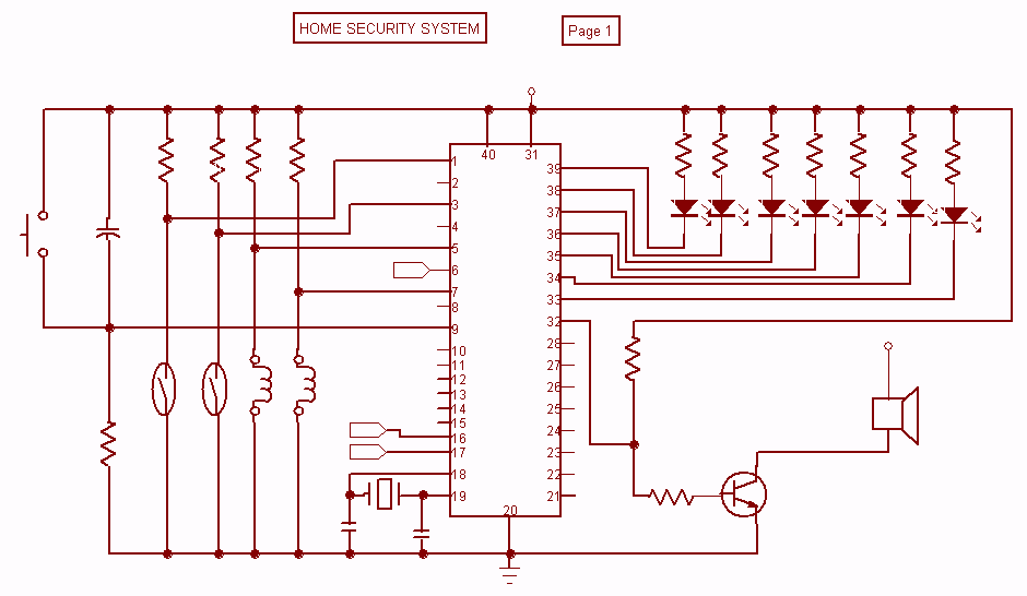
Home Security System with microcontroller
Security is a prime concern in our day-to-day life. Everyone wants to be as much secure as possible. An access control for doors forms a vital link in a security chain. The Microcontroller based Home Security System can be adopted...

Robot Motor Control Schematic
The schematic for controlling the motors is divided into three main sections, each serving a distinct function. The primary components featured in the schematic include the PIC 18F252 microcontroller, the SN754410 motor driver, and 2N2222 transistors. At the top of...
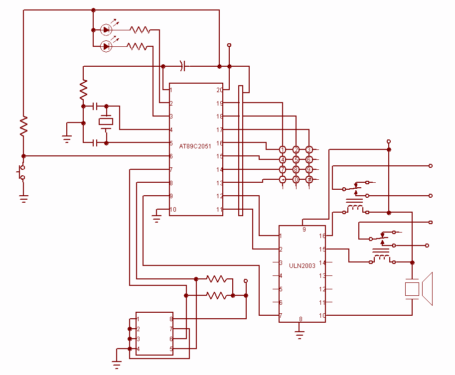
Password Based Door Locking
Security is a prime concern in our day-to-day life. Everyone wants to be as much secure as possible. An access control for doors forms a vital link in a security chain. The microcontroller based Door locker is an access control...