


Pseudo-Random Bit Sequence Generator Circuit
#pseudo-random
#bit sequence
#shift-register
#feedback loop
#exclusive-OR gate
#maximal length sequence
#digital
#logic
#generator

Description: In this circuit, an additional exclusive-OR gate is connected after the modulo-2 feedback, with CI and R2 applying the supply turn-on ramp into the feedback loop. This provides sufficient transient signal so that the PRBS generator can self-start during power-up. A shift-register length of 10 is shown with feedback at stages 3 and 10, providing true and inverted maximal length sequence outputs. This technique applies an input directly to the feedback loop. Therefore, it is considered more reliable than applying an RC configuration to the shift-register reset input to create a random turn-on state.
The circuit design incorporates an exclusive-OR gate positioned after a modulo-2 feedback mechanism, which plays a crucial role in the operation of a Pseudo-Random Binary Sequence (PRBS) generator. The configuration utilizes components CI and R2 to introduce a supply turn-on ramp into the feedback loop, effectively generating a transient signal. This transient signal is essential for enabling the PRBS generator to initiate its operation autonomously upon power-up, ensuring reliable performance.
The shift register in this design has a length of 10, with feedback connections established at stages 3 and 10. This arrangement allows for the generation of both true and inverted maximal length sequence outputs, which are fundamental for various digital communication applications. The direct application of input to the feedback loop is a significant aspect of this design, as it enhances the reliability of the circuit. Unlike traditional methods that utilize an RC configuration for resetting the shift register, which can lead to unpredictable initial states, the current approach ensures a more deterministic behavior during startup.
This circuit is particularly advantageous in scenarios where consistent and repeatable operation of the PRBS generator is required. The careful selection of feedback stages and the implementation of the exclusive-OR gate contribute to the overall stability and performance of the system, making it suitable for high-speed digital applications. The design emphasizes the importance of transient signals in circuit initialization and the benefits of direct feedback mechanisms in enhancing operational reliability. In this circuit, an additional exclusive-OR gate is connected after the modulo-2 feedback, with CI and R2 applying the supply turn-on ramp into the feedback loop. This provides sufficient transient signal so that the PRBS generator can self-start a power-up. A shift-register length of 10 is shown with feedback at stages 3 and 10, providing true and inverted maximal length sequence outputs.
This technique applies an input directly to the feedback loop. Therefore, it`s considered more reliable than applying an RC configuration to the shift-register reset input to create a random turn-on state.
The circuit design incorporates an exclusive-OR gate positioned after a modulo-2 feedback mechanism, which plays a crucial role in the operation of a Pseudo-Random Binary Sequence (PRBS) generator. The configuration utilizes components CI and R2 to introduce a supply turn-on ramp into the feedback loop, effectively generating a transient signal. This transient signal is essential for enabling the PRBS generator to initiate its operation autonomously upon power-up, ensuring reliable performance.
The shift register in this design has a length of 10, with feedback connections established at stages 3 and 10. This arrangement allows for the generation of both true and inverted maximal length sequence outputs, which are fundamental for various digital communication applications. The direct application of input to the feedback loop is a significant aspect of this design, as it enhances the reliability of the circuit. Unlike traditional methods that utilize an RC configuration for resetting the shift register, which can lead to unpredictable initial states, the current approach ensures a more deterministic behavior during startup.
This circuit is particularly advantageous in scenarios where consistent and repeatable operation of the PRBS generator is required. The careful selection of feedback stages and the implementation of the exclusive-OR gate contribute to the overall stability and performance of the system, making it suitable for high-speed digital applications. The design emphasizes the importance of transient signals in circuit initialization and the benefits of direct feedback mechanisms in enhancing operational reliability. In this circuit, an additional exclusive-OR gate is connected after the modulo-2 feedback, with CI and R2 applying the supply turn-on ramp into the feedback loop. This provides sufficient transient signal so that the PRBS generator can self-start a power-up. A shift-register length of 10 is shown with feedback at stages 3 and 10, providing true and inverted maximal length sequence outputs.
This technique applies an input directly to the feedback loop. Therefore, it`s considered more reliable than applying an RC configuration to the shift-register reset input to create a random turn-on state.

Digital pulse width measurement circuit diagram CD4518 and CD4069 the
A digital pulse width measurement circuit is presented. It operates with a 100 kHz reference frequency to count the pulse width of the input signal. The count value represents the measured pulse width displayed on four seven-segment LED displays. The...

The 6090 Digital Decoder
This is an image Schematic. No Description available.
The provided input indicates that there is a schematic image, but no additional descriptive information is available regarding its components, functionality, or application. In the context of electronic schematics, such images typically...
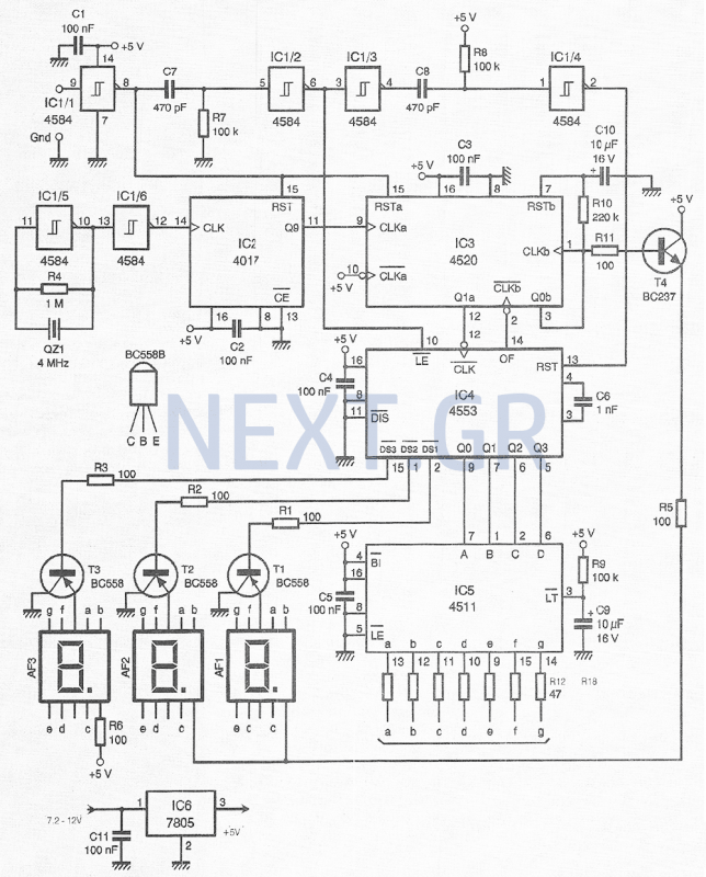
High Precision Digital Pulse Meter Circuit
This compact device, designed primarily for modelers, provides instantaneous readings of pulse duration in milliseconds (ms). It can measure servomotor positions, typically ranging from 1 ms to 2 ms, and can also perform repetitive or non-pulsed measurements, such as the...

equalizer circuit
An electrical circuit that ensures when two or more generators are connected in parallel to a power system, they share the load equally. In this arrangement, if the voltage of one generator is slightly higher than that of the other...

From the same period and vehicle route map
Vehicles from the same period utilize a generator without excitation, which means there is no voltage generator bus, only residual voltage (approximately ten volts). This makes operation relatively simple. It is necessary to wait until the generator speed (frequency) rises...

Auto Generator Regulator Circuit
This regulator is designed to control a DC generator. In this configuration, one side of the field is grounded. Diode D4 prevents the battery from discharging through the generator and serves as a replacement for the mechanical cut-out relay. The...

Self runner Generator
The timing must be exact to get those high voltage spikes. I used a tiny magnet on the rotor, that triggered a reed switch allowing the relay to pulse the energy from the recovery coil to the primary battery. In...

Homemade Digital CALL-ID English Version
The reason for this project was to facilitate a quick installation for a local friend 10 km away, enabling the start of real-life testing to identify and resolve bugs and problems before releasing it to other users. The software is...

A small generator and network control circuit
Circle i represents a two-phase grid connection line for an AC technology turbine shed, which consists of two lines. A voltage is generated between Ri through a Buck converter, with components R1 and R3 dividing the output. The sampled level...