


Set reset flip-flop circuit
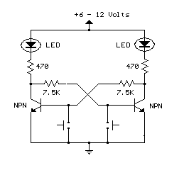
Description: This is an example of a set/reset flip flop using discrete components. When power is applied, only one of the transistors will conduct causing the other to remain off. More: The conducting transistor can be turned off by grounding its base through the push button which causes the collector voltage to rise and turn on the opposite transistor.
The described circuit is a basic set/reset flip flop configuration utilizing discrete bipolar junction transistors (BJTs). The flip flop consists of two NPN transistors, labeled Q1 and Q2, which are cross-coupled to form a bistable multivibrator.
Upon application of power, one of the transistors will enter the active region, allowing current to flow from the collector to the emitter, while the other transistor remains in the cutoff region. This state is determined by the initial conditions or any small signal present at the bases of the transistors.
To implement the reset functionality, a push button switch is connected to the base of the conducting transistor. When the push button is pressed, it connects the base of the conducting transistor to ground, effectively turning it off. As a result, the collector voltage of this transistor rises, which is coupled to the base of the opposite transistor. This causes the second transistor to turn on, thus changing the state of the flip flop.
The circuit can be powered by a DC voltage source, typically between 5V to 15V, depending on the specifications of the transistors used. Resistors are employed at the bases of the transistors to limit the base current and ensure proper biasing. Capacitors may also be included to improve stability and reduce noise in the circuit.
This discrete flip flop configuration is widely used in digital electronics for applications requiring state retention, such as memory storage, toggle switches, and simple control systems. The simplicity of the design allows for easy troubleshooting and understanding of fundamental digital logic principles.This is an example of a set/reset flip flop using discrete components. When power is applied, only one of the transistors will conduct causing the other to remain off. The conducting transistor can be turned off by grounding it's base through the push button which causes the collector voltage to rise and turn on the opposite transistor.
The described circuit is a basic set/reset flip flop configuration utilizing discrete bipolar junction transistors (BJTs). The flip flop consists of two NPN transistors, labeled Q1 and Q2, which are cross-coupled to form a bistable multivibrator.
Upon application of power, one of the transistors will enter the active region, allowing current to flow from the collector to the emitter, while the other transistor remains in the cutoff region. This state is determined by the initial conditions or any small signal present at the bases of the transistors.
To implement the reset functionality, a push button switch is connected to the base of the conducting transistor. When the push button is pressed, it connects the base of the conducting transistor to ground, effectively turning it off. As a result, the collector voltage of this transistor rises, which is coupled to the base of the opposite transistor. This causes the second transistor to turn on, thus changing the state of the flip flop.
The circuit can be powered by a DC voltage source, typically between 5V to 15V, depending on the specifications of the transistors used. Resistors are employed at the bases of the transistors to limit the base current and ensure proper biasing. Capacitors may also be included to improve stability and reduce noise in the circuit.
This discrete flip flop configuration is widely used in digital electronics for applications requiring state retention, such as memory storage, toggle switches, and simple control systems. The simplicity of the design allows for easy troubleshooting and understanding of fundamental digital logic principles.This is an example of a set/reset flip flop using discrete components. When power is applied, only one of the transistors will conduct causing the other to remain off. The conducting transistor can be turned off by grounding it's base through the push button which causes the collector voltage to rise and turn on the opposite transistor.

intercom circuit with transistors
The key to avoiding instability (motor-boating) in a high-gain circuit is to power the speaker using a separate power supply. This circuit design allows for the connection of one or two additional stations. It is recommended to construct the circuit...

Oscillators and Triggers
Transistors are increasingly being utilized in various applications. Many circuits employing transistors have been developed based on previous designs that used vacuum tubes. The following chapters present unique applications that leverage the advantageous properties of transistors. The described circuits are...

Practical flip-flop circuit
A flip-flop circuit with a memory function for pulse signals. It features two stable states: one where transistor VTi is off and VTZ is conducting, and another where VTi is conducting and VT2 is off. An external signal is sufficient...

motorola hi fi power
The first step is to measure the amplification factor of the end transistors (T3 and T4), known as the hfe. If their difference exceeds 30%, the amplifier will produce unclear sound. In this case, MJ3001 and MJ2501 transistors were used,...

flipflop Purpose of the logic gate configurations on the Kenbak-1
This text discusses the functionality of a flip-flop, specifically focusing on the role of two NAND gates and the presence of an additional inverter. It suggests allowing time for others to analyze the question and formulate their theories, emphasizing that...

1 Kw flip-flop flasher circuit
This application involves a static switch circuit where the control logic is implemented using a flip-flop, which is driven by a unijunction transistor. The flashing rate of the circuit can be adjusted, ranging from approximately 0.1 seconds to a 10-second...

inverter circuit diagram
A common topology for DC-AC power converter circuits employs a pair of transistors to switch DC current through the center-tapped winding of a step-up transformer. Examine the check plot images from a PCB drafting program for a control board based...

Flip-Flop Debouncer Switch
This circuit utilizes a 74HC74 flip-flop, although any CMOS variant of this component can be employed. IC1A functions as a true/complement buffer. Resistors R1 and R2 ensure that IC1A exits the reset state prior to the clock edge occurrence. Resistor...
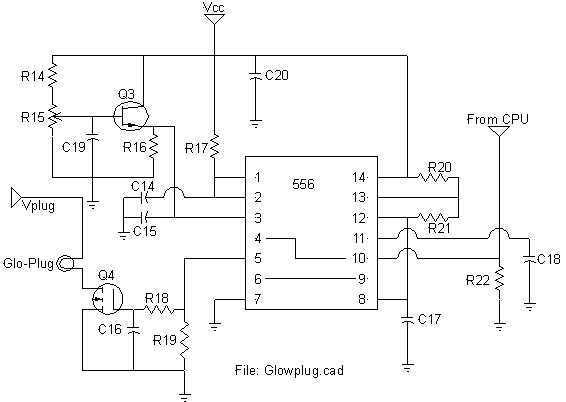
Logic adjustable Glow-Plug drive
All of my turbine starts before the research on the ECU involved a very successful spark ignition. I thought (only briefly) of trying to add spark ignition to the ECU, but the mixture of delicate logic circuitry and perhaps 30,000V...