


Simple 7-Segment Counter Circuit
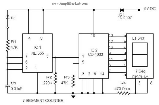
Description: The circuit diagram of a 7-segment counter circuit has been published here. This circuit consists of the counter IC CD4033 as its central component.
The 7-segment counter circuit utilizing the CD4033 integrated circuit (IC) is designed to display decimal digits from 0 to 9 on a 7-segment display. The CD4033 is a BCD (Binary-Coded Decimal) counter that can drive a 7-segment display directly, making it an ideal choice for this application.
The circuit typically includes the following components: the CD4033 IC, a 7-segment display, resistors for current limiting, and a clock signal source, which can be generated by a 555 timer or any other clock generator circuit. The CD4033 operates by counting pulses received at its clock input, incrementing the count with each pulse.
The output of the CD4033 is in binary-coded decimal format, which is then decoded to drive the 7-segment display. Each output pin of the CD4033 corresponds to a specific segment of the 7-segment display, allowing the display to represent the counted number visually.
Power supply connections are also essential; the CD4033 requires a DC power supply, typically in the range of 3V to 15V. Proper grounding and bypass capacitors should be included to ensure stable operation.
In summary, the 7-segment counter circuit employing the CD4033 IC is a straightforward yet effective design for visual numerical representation, suitable for various applications such as timers, clocks, and digital counters.The circuit diagram of 7 segment counter circuit has been published here. This circuit consists of counter IC CD 4033 as its central part.
The 7-segment counter circuit utilizing the CD4033 integrated circuit (IC) is designed to display decimal digits from 0 to 9 on a 7-segment display. The CD4033 is a BCD (Binary-Coded Decimal) counter that can drive a 7-segment display directly, making it an ideal choice for this application.
The circuit typically includes the following components: the CD4033 IC, a 7-segment display, resistors for current limiting, and a clock signal source, which can be generated by a 555 timer or any other clock generator circuit. The CD4033 operates by counting pulses received at its clock input, incrementing the count with each pulse.
The output of the CD4033 is in binary-coded decimal format, which is then decoded to drive the 7-segment display. Each output pin of the CD4033 corresponds to a specific segment of the 7-segment display, allowing the display to represent the counted number visually.
Power supply connections are also essential; the CD4033 requires a DC power supply, typically in the range of 3V to 15V. Proper grounding and bypass capacitors should be included to ensure stable operation.
In summary, the 7-segment counter circuit employing the CD4033 IC is a straightforward yet effective design for visual numerical representation, suitable for various applications such as timers, clocks, and digital counters.The circuit diagram of 7 segment counter circuit has been published here. This circuit consists of counter IC CD 4033 as its central part.

8-Digit up-down counter
This circuit illustrates the method of cascading counters while maintaining the appropriate leading zero blanking. A NAND gate is employed to determine if a digit is active, as indicated by the activation of either segment a or b on any...

Simple Digital Logic Probe Circuit
The design of the digital logic probe centers around a pair of complementary bipolar transistors, which, in this application, are used as electronic switches.
The digital logic probe is a diagnostic tool utilized for testing and analyzing digital circuits. The core...
ELECTRONIC DICE
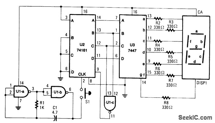
When S1 is pressed, counter U2 is activated by oscillator U1A/U1B, and the count (ranging from 0 to 6) is displayed on DISP1. The resistor R1 and capacitor C1 define the count rate, which must be sufficiently rapid to produce...

up down counter circuit
This circuit diagram illustrates a simple up/down counter suitable for various applications. It utilizes the CD40110BE IC, a CMOS decade up/down counter. Common cathode seven-segment displays are connected to the outputs of each IC. The display connected to IC1 shows...

Digital Oil-Pressure Gauge
This gauge utilizes a sensor along with resistor R1 to generate a DC voltage that is proportional to oil pressure. Integrated circuits IC1 and IC2 form a two-digit digital voltmeter (DVM). Transistors Q1 and Q2 act as display selectors for...

RING COUNTER WITH VISUAL READOUT
The circuit utilizes only six components per stage. By integrating counter and indicator functions, it achieves low battery consumption. Once the reset button is released, a 0.22 µF capacitor ensures that the first stage activates. Current is drawn by the...
PSIM Training CD-ROMs
The counter is programmed to function in a batch-counting operation, automatically sorting parts for quality control. It is designed to divert one part out of every ten for the quality control or inspection process. The circuit operates as described.
The automatic...

Ic Product Detectors
These product detectors utilize integrated circuit (IC) devices. They are capable of detecting single sideband (SSB) and continuous wave (CW) signals. The circuits are designed to operate effectively up to frequencies of 20 or 30 MHz. T3 in the schematic...

12V 5MHz COUNTER
The portable counter is designed with low-power logic to minimize battery drain while maintaining good performance. Since most of the milliwatt power drain is consumed by the digital readout, the circuit blanks the LED display when there is no input...