


Single-Dual digital LED dice circuit
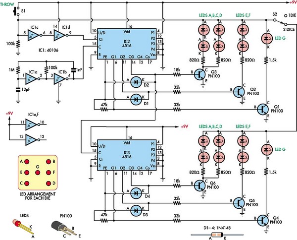
Description: This circuit utilizes two 4516 integrated circuits (ICs) to simulate a game involving two dice. A switch is included to select whether one or two dice will be activated with each press. A 9-volt battery is sufficient for power supply. It is recommended to construct a compact enclosure and arrange the LEDs according to the provided diagram.
The circuit design employs two 4516 ICs, which are dual 4-bit binary counters. These counters will effectively simulate the random output of dice rolls by generating binary numbers that correspond to the values of the dice. Each IC can count from 0 to 15, but for the purpose of simulating dice, the outputs will be limited to the range of 1 to 6, which can be achieved through additional logic circuitry.
The switching mechanism allows the user to select between one or two dice rolls. This can be implemented using a single-pole double-throw (SPDT) switch that alters the circuit configuration to enable either one or both counters. When the switch is set to one die, only one of the 4516 ICs will be active, while the second IC remains inactive. Conversely, when the switch is set to two dice, both ICs will be engaged, and their outputs will be displayed simultaneously.
Powering the circuit with a 9-volt battery provides adequate voltage for the 4516 ICs, ensuring reliable operation. The circuit should include appropriate decoupling capacitors near the power pins of the ICs to minimize noise and improve stability.
The output of the counters will be displayed using LEDs, which will visually represent the results of the dice rolls. Each die's output will be connected to a set of LEDs arranged in a manner that corresponds to the numbers 1 through 6. The design should ensure that only one LED lights up at a time for each die, representing the rolled value. This can be accomplished using a combination of resistors and transistors to control the current flowing to each LED based on the binary output from the ICs.
The construction of the circuit within a small enclosure will not only enhance portability but also provide protection to the components. Careful attention should be paid to the layout to ensure that all connections are secure and that the LEDs are positioned according to the schematic diagram for optimal visibility.By using two 4516 ICs, this circuit will simulate two dices playing game. There is a switch to choose if one or two dices will be run at each throw pressing. A 9 volt battery willl be ok. Make a nice small box and place the LEDS acorcding to the diagram shown.
The circuit design employs two 4516 ICs, which are dual 4-bit binary counters. These counters will effectively simulate the random output of dice rolls by generating binary numbers that correspond to the values of the dice. Each IC can count from 0 to 15, but for the purpose of simulating dice, the outputs will be limited to the range of 1 to 6, which can be achieved through additional logic circuitry.
The switching mechanism allows the user to select between one or two dice rolls. This can be implemented using a single-pole double-throw (SPDT) switch that alters the circuit configuration to enable either one or both counters. When the switch is set to one die, only one of the 4516 ICs will be active, while the second IC remains inactive. Conversely, when the switch is set to two dice, both ICs will be engaged, and their outputs will be displayed simultaneously.
Powering the circuit with a 9-volt battery provides adequate voltage for the 4516 ICs, ensuring reliable operation. The circuit should include appropriate decoupling capacitors near the power pins of the ICs to minimize noise and improve stability.
The output of the counters will be displayed using LEDs, which will visually represent the results of the dice rolls. Each die's output will be connected to a set of LEDs arranged in a manner that corresponds to the numbers 1 through 6. The design should ensure that only one LED lights up at a time for each die, representing the rolled value. This can be accomplished using a combination of resistors and transistors to control the current flowing to each LED based on the binary output from the ICs.
The construction of the circuit within a small enclosure will not only enhance portability but also provide protection to the components. Careful attention should be paid to the layout to ensure that all connections are secure and that the LEDs are positioned according to the schematic diagram for optimal visibility.By using two 4516 ICs, this circuit will simulate two dices playing game. There is a switch to choose if one or two dices will be run at each throw pressing. A 9 volt battery willl be ok. Make a nice small box and place the LEDS acorcding to the diagram shown.

Novel White LED Torch
This design is directly derived from the manufacturer's datasheets, but its application is relatively novel. Initially intended for high-visibility LED bargraph readouts, the LM3914 is utilized here as the foundation for a 10-step variable brightness current-regulated white LED torch. The...

Using AC for LED Christmas Lights
This circuit utilizes low-voltage AC to power a string of approximately 50 bi-color LEDs, with two LEDs connected in inverse parallel. The power supplied to the LEDs is managed by a Triac and two optocouplers, whose phototransistors are also connected...

KNIGHT RIDER lights
The circuit consists of two building blocks. The first is a square wave oscillator made up of two transistors in a multivibrator arrangement and the second is a CD 4017 decade counter IC. The multivibrator contains two extra components to...

Precision LED Blinker
The circuit allows a precision regulated drive current to be set to drive an LED, and in response to a TTL level signal, the LED is switched on and off with rise and fall times of less than 500 nanoseconds...

Traffic Light Project
This project operates red, amber, and green LEDs in the correct sequence for a single UK traffic light. The duration of the complete sequence—red, red & amber, green, amber—can be adjusted from approximately 7 seconds to about 2.5 minutes by...
reverse engineer a LED light bulb
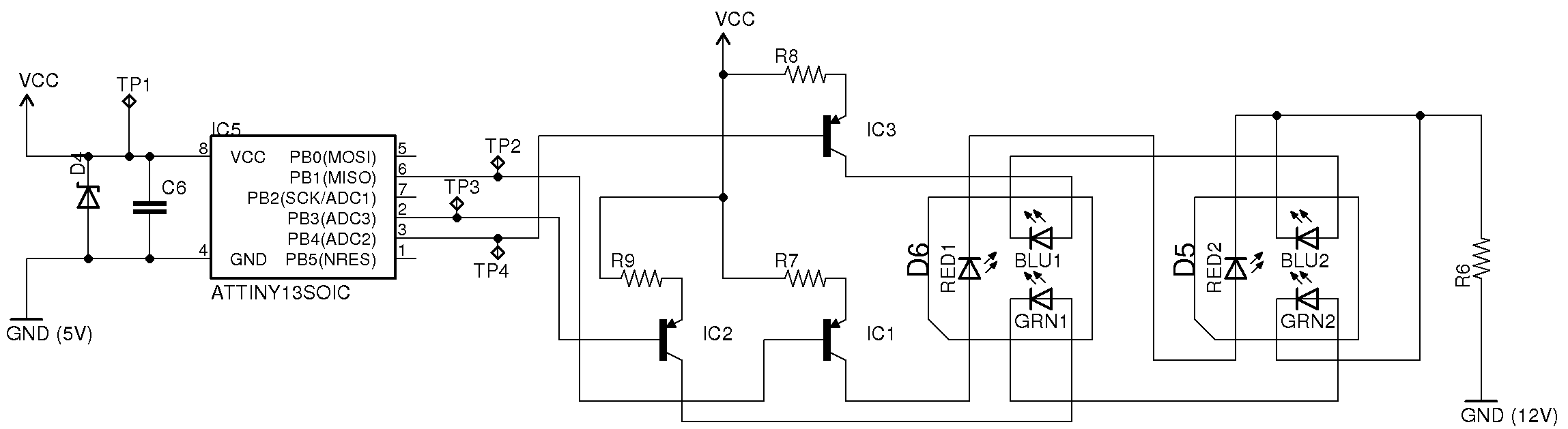
Approximately one month ago, an attempt was made to reverse engineer a low-cost LED color-changing light bulb. With assistance, the circuit has been mapped out, and control over the bulb has been established. However, several aspects of this device remain...

LED Boost Circuit
The completed board may be driven by voltages between 0.8 and 3 Volts. While the basic design goal was candle-like light from a single cell, the values used were chosen to allow safe operation from 3 Volts so you can,...

Reuse Old Mobile Phone Battery for LED lighting
Mobile batteries typically have a lifespan of 2 to 5 years under normal usage, after which they need to be replaced. Currently, inexpensive replacement batteries are available for about $1, but these low-cost options only last 6 to 12 months....

Chase circuit loop type lights
This example demonstrates a robust design featuring novelty lights that flash in a specific sequence, utilizing a 1-3-2-4 vault chase mode. The circuit includes diodes VD1 to VD4, which form a bridge rectifier, converting AC voltage to a full-wave rectified...