


Static 0 to 9 Display using SN7446 and 7490
#SN7446
#7490
#7-segment display
#decade counter
#decoder/driver
#LED
#static display
#digital counter
#logic IC
#0-9 display
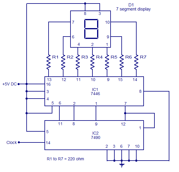
Description: The circuit presented is a basic static 0-9 display that can be utilized in various applications. It is based on the 7490 asynchronous decade counter (IC2), a 7-segment display (D1), and a seven-segment decoder/driver IC 7446 (IC1). The seven-segment display comprises seven LEDs labeled from 'a' to 'g', which can represent the digits 0 to 9 through different LED biases. There are two types of seven-segment displays: common cathode and common anode. In a common anode type, the anodes of all seven LEDs are connected together, while in a common cathode type, the cathodes are connected together. The seven-segment display utilized in this circuit is of the common anode variety. Resistors R1 to R7 serve as current limiting resistors. The IC 7446 functions as a decoder/driver IC that manages the seven-segment display. The operation of this circuit is straightforward; for each clock pulse, the output of the IC2 BCD (7490) advances by one bit. The IC1 (7446) decodes the BCD output into a format suitable for the seven-segment display, thereby controlling the display to show the corresponding digit.
The circuit operates by clocking the 7490 IC, which is a binary-coded decimal (BCD) counter. Each clock pulse increments the counter's output, which ranges from 0000 (0) to 1001 (9). The output is then sent to the IC7446, which interprets the BCD input and translates it into signals that illuminate the appropriate segments of the seven-segment display.
In a common anode display, the anodes of the LEDs are connected to a positive voltage supply, while the cathodes are connected to the outputs of the 7446 decoder. When the decoder activates a specific output corresponding to a digit, it connects the respective cathodes to ground, allowing current to flow through the anodes and illuminating the segments required to form the desired numeral.
The current limiting resistors (R1 to R7) are crucial for protecting the LEDs from excessive current, which could lead to overheating and failure. The values of these resistors can be calculated based on the forward voltage of the LEDs and the supply voltage to ensure that the current remains within safe limits, typically around 20 mA for standard LEDs.
Overall, this circuit is a practical and efficient way to display numerical information in a clear and visually appealing manner, suitable for various electronic projects and applications where numerical output is required.The circuit shown here is a simple Static 0-9 Display can be used in many applications. The circuit is based on 7490 asynchronous decade counter (IC2), a 7-segment display (D1), and a seven-segment decoder / driver IC 7446 (IC1). The seven-segment display consists of 7 LEDs as `a` to `g`. For different LEDs bias, we can show the digits 0 to 9. Sev en Segment Displays are of two types, the common cathode and common anode. Like the type of anode anodes of all seven LEDs are attached, while the type common cathode cathodes are all together. The seven-segment display used here is a type common anode. The resistance R1 to R7 are current limiting resistors. IC 7446 is a decoder / driver IC that is used to control the seven segment display. Work of this circuit is very simple. For each clock pulse output of IC2 BCD (7490) advances a bit. The IC1 (7446) decodes the BCD output for the form of seven segments and controlling the display to indicate the corresponding digit.
The circuit operates by clocking the 7490 IC, which is a binary-coded decimal (BCD) counter. Each clock pulse increments the counter's output, which ranges from 0000 (0) to 1001 (9). The output is then sent to the IC7446, which interprets the BCD input and translates it into signals that illuminate the appropriate segments of the seven-segment display.
In a common anode display, the anodes of the LEDs are connected to a positive voltage supply, while the cathodes are connected to the outputs of the 7446 decoder. When the decoder activates a specific output corresponding to a digit, it connects the respective cathodes to ground, allowing current to flow through the anodes and illuminating the segments required to form the desired numeral.
The current limiting resistors (R1 to R7) are crucial for protecting the LEDs from excessive current, which could lead to overheating and failure. The values of these resistors can be calculated based on the forward voltage of the LEDs and the supply voltage to ensure that the current remains within safe limits, typically around 20 mA for standard LEDs.
Overall, this circuit is a practical and efficient way to display numerical information in a clear and visually appealing manner, suitable for various electronic projects and applications where numerical output is required.The circuit shown here is a simple Static 0-9 Display can be used in many applications. The circuit is based on 7490 asynchronous decade counter (IC2), a 7-segment display (D1), and a seven-segment decoder / driver IC 7446 (IC1). The seven-segment display consists of 7 LEDs as `a` to `g`. For different LEDs bias, we can show the digits 0 to 9. Sev en Segment Displays are of two types, the common cathode and common anode. Like the type of anode anodes of all seven LEDs are attached, while the type common cathode cathodes are all together. The seven-segment display used here is a type common anode. The resistance R1 to R7 are current limiting resistors. IC 7446 is a decoder / driver IC that is used to control the seven segment display. Work of this circuit is very simple. For each clock pulse output of IC2 BCD (7490) advances a bit. The IC1 (7446) decodes the BCD output for the form of seven segments and controlling the display to indicate the corresponding digit.

USB Blinky
Projects often involve numerous LEDs and microcontrollers; however, there is appreciation for simpler implementations using LEDs. One of the most basic LED circuits is...
A basic LED circuit can be constructed using a single LED, a current-limiting resistor, and a power...

simple current controlled led tube
The circuit of a current-controlled LED tube light employs high-voltage transistors to implement the necessary current control operation based on a fundamental principle. A resistor (R2) is utilized to convert the increasing current into a voltage across itself. This voltage...

1A Low Noise High Current LED Torch/Flash
An ultralow dropout current source maintains accurate LED current at very low ILED voltages. Automatic mode switching optimizes efficiency by monitoring the voltage across the LED current source and switching modes only when ILED dropout is detected. The LTC3216 is...

The LED car voltmeter (2)
This document introduces an LED car voltmeter constructed using the op-amp LM312 and LED components. It is designed to display six voltage levels ranging from 10V to 15V, with each level representing a 1V increment. The working principle of the...

Regulated 24 Watt Broad Spectrum LED
This project involves constructing an energy-efficient broad spectrum LED lamp system designed for indoor reflective room lighting. The lamp provides a broad color spectrum that closely resembles natural sunlight compared to fluorescent bulbs and white-only LEDs. The light output is...

LED As Photodiode
In the project LED Touch Sensing by Jeff Han, a remarkable phenomenon occurs with an LED matrix that not only illuminates but also detects finger touches. Initially, it was assumed that a special type of LED matrix was utilized, but...

New Knight Rider LED Board
The TL082 (Or a TL072 also is OK) Creates an Adjustable Sawtooth Generator. (It also has a Square wave Output, but it isn`t used here.)
The Left and Right LEDs are connected in series, and if this circuit is used on...

LED light
The goal was to create a compact flashlight that could be held in the mouth, easily stored in a pocket, and positioned on a surface to project light upwards. The budget was set at approximately $15, which was significantly lower...
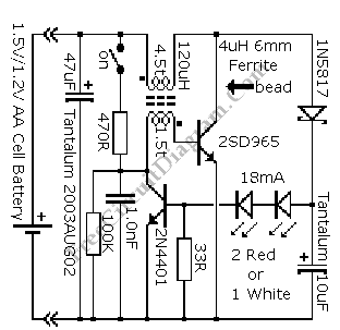
Powering LED from Single AA Cell
The advantage of LED technology is its longer lifespan compared to incandescent lamps, along with higher efficiency in the latest LED advancements. Additionally, LEDs are very compact; however, there are some limitations.
LEDs, or Light Emitting Diodes, are semiconductor devices that...