


Step Switch Selector
#analogue switch
#step switch
#selector
#multiplexer
#digital control
#circuit switching
#signal routing
#control logic
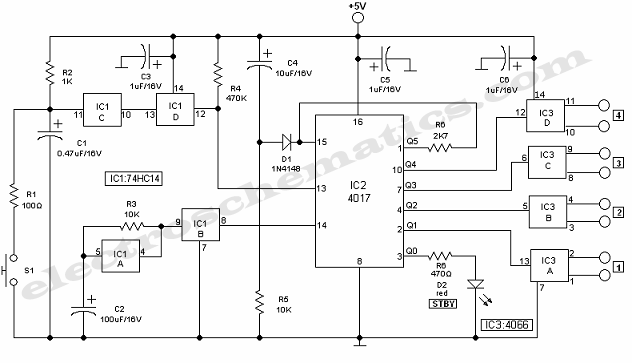
Description: The step switch selector circuit is designed to select one of up to four analog switches, utilizing specific components for its operation.
The step switch selector circuit functions by employing a mechanical or electronic stepping mechanism to sequentially activate one of several analog switches. This type of circuit is often used in applications where multiple signal paths need to be selected without the need for complex control systems.
Typically, the circuit includes a rotary switch or a push-button interface that allows the user to select the desired switch position. Each position corresponds to a unique analog switch, which in turn connects the input signal to the output path. The analog switches can be implemented using MOSFETs, analog multiplexers, or dedicated analog switch ICs, depending on the required specifications such as voltage levels, current ratings, and switching speed.
The control logic for the step switch can be implemented using simple combinational logic circuits or microcontrollers, depending on the complexity of the application. For example, a microcontroller can provide additional features such as automatic switching based on predefined conditions or user interfaces.
Power supply considerations are also crucial in the design of this circuit. The voltage levels must be compatible with the analog switches and the signals being routed. Decoupling capacitors may be used to filter out noise and ensure stable operation.
In summary, the step switch selector circuit is a versatile solution for selecting among multiple analog paths, offering flexibility and ease of use in various electronic applications.As the name indicates, the step switch selector circuit is intended to choose one of up to four analogue switches, which it does with the aid of some less..
The step switch selector circuit functions by employing a mechanical or electronic stepping mechanism to sequentially activate one of several analog switches. This type of circuit is often used in applications where multiple signal paths need to be selected without the need for complex control systems.
Typically, the circuit includes a rotary switch or a push-button interface that allows the user to select the desired switch position. Each position corresponds to a unique analog switch, which in turn connects the input signal to the output path. The analog switches can be implemented using MOSFETs, analog multiplexers, or dedicated analog switch ICs, depending on the required specifications such as voltage levels, current ratings, and switching speed.
The control logic for the step switch can be implemented using simple combinational logic circuits or microcontrollers, depending on the complexity of the application. For example, a microcontroller can provide additional features such as automatic switching based on predefined conditions or user interfaces.
Power supply considerations are also crucial in the design of this circuit. The voltage levels must be compatible with the analog switches and the signals being routed. Decoupling capacitors may be used to filter out noise and ensure stable operation.
In summary, the step switch selector circuit is a versatile solution for selecting among multiple analog paths, offering flexibility and ease of use in various electronic applications.As the name indicates, the step switch selector circuit is intended to choose one of up to four analogue switches, which it does with the aid of some less..

Mux-Demux system
Multiple signals can be transmitted between two locations at the same time by making a minor adjustment to the receiver circuit. An additional DG508A is employed as a demultiplexer, enabling continuous monitoring of all 8 channels.
To implement a system for...

INVERTER_AND_PULSE_STRETCHER
The circuit samples the output of a multiplexer and provides the necessary current for driving a transfluxor in an analog-to-digital converter that generates a six-bit binary Gray code. -N. Aron and C. Granger, Analog-To-Digital Converter Uses Transfluxors, Electronics, 35:20, p...

TIPE Project
A simple non-commercial grade multiplexer compatible with telephones. It will support four telephone lines and will multiplex over one cable. The topic was free of choice but had to be oriented around the theme of "PrG©vision" (prediction). As anticipated, the...

2-to-1 Multiplexer
The 8-bit 2x1 multiplexer comprises 16 tristate buffers and a static inverter. It is configured such that when the select bit is low, 8 of the input bits are transmitted through the tristate buffers to the 8 output bits. Conversely,...

Analog multiplexer CD4051 extension circuit 1
The CD4051 is a single-ended input 8-channel multiplexer that features three channel select inputs (A, B, C) and an inhibit input (INH). The signals at inputs A, B, and C are utilized to control the selection of one of the...

8 way electronic selector / switch
The Elect. Sel. 8 is a simple circuit, with a choice of 8 sources of any sort, of 8 independent switches. Each switch corresponding with a relay for example the switch S1 activates the RL1 etc. The uses of the...

Digital lighting circuit
After the SCM execution, the Pl output port connects to the bidirectional input of 74LS245 driver chips. This driver operates during each phase of digital control, based on the information from the Pl port. The purpose is to convert characters...

IC Multiplexers
There is a lack of clarity regarding the difference between a data selector and a multiplexer. The designs previously engaged in ceased utilizing small-scale integrated circuits in the early 1990s, as the physical aspect transitioned to general-purpose programmable array logic...

Electronic 10 way Selector Relays
This is a circuit for alternative sources selection. It combines mechanical selection using a rotating switch S1, the electronic drive of the relays RL 1-10 and also the optical indication of the selection by the Display DSP1. The function is...