


Symmetrical division circuit diagram
#4013
#D-type flip-flop
#astable multivibrator
#binary divider
#frequency division
#symmetrical output
#digital circuits

Description: The 4013 pairs of D-type flip-flops in the astable multivibrator configuration are utilized as a binary divider output, generating an output frequency that is symmetrical, with a duty cycle of 50%.
The 4013 integrated circuit contains two D-type flip-flops that can be configured to operate in an astable multivibrator mode. In this configuration, the flip-flops continuously toggle between high and low states, producing a square wave output. This square wave signal serves as a clock pulse for various digital circuits and applications.
The astable multivibrator setup involves connecting the output of one flip-flop to the clock input of the other. This arrangement effectively divides the input frequency by two, allowing the circuit to produce an output frequency that is half of the input frequency. The symmetrical nature of the output ensures that the high and low states are equal in duration, resulting in a duty cycle of 50%.
To achieve the desired frequency, external resistors and capacitors are connected to the flip-flops, determining the timing characteristics of the oscillation. The frequency of oscillation can be calculated using the formula:
\[ f = \frac{1}{2 \times R \times C} \]
where \( R \) represents the resistance and \( C \) represents the capacitance in the timing network. By adjusting these components, the output frequency can be fine-tuned for specific applications.
The 4013 D-type flip-flops are suitable for various digital applications, including frequency dividers, pulse generators, and clock signal generation. Their versatility and reliability make them a valuable component in digital circuit design.4013 pairs of D-type flip-flop in the astable multivibrator is used as a binary divider output, will produce the output frequency of the multivibrator frequency symmetrical hal f 50/50.
The 4013 integrated circuit contains two D-type flip-flops that can be configured to operate in an astable multivibrator mode. In this configuration, the flip-flops continuously toggle between high and low states, producing a square wave output. This square wave signal serves as a clock pulse for various digital circuits and applications.
The astable multivibrator setup involves connecting the output of one flip-flop to the clock input of the other. This arrangement effectively divides the input frequency by two, allowing the circuit to produce an output frequency that is half of the input frequency. The symmetrical nature of the output ensures that the high and low states are equal in duration, resulting in a duty cycle of 50%.
To achieve the desired frequency, external resistors and capacitors are connected to the flip-flops, determining the timing characteristics of the oscillation. The frequency of oscillation can be calculated using the formula:
\[ f = \frac{1}{2 \times R \times C} \]
where \( R \) represents the resistance and \( C \) represents the capacitance in the timing network. By adjusting these components, the output frequency can be fine-tuned for specific applications.
The 4013 D-type flip-flops are suitable for various digital applications, including frequency dividers, pulse generators, and clock signal generation. Their versatility and reliability make them a valuable component in digital circuit design.4013 pairs of D-type flip-flop in the astable multivibrator is used as a binary divider output, will produce the output frequency of the multivibrator frequency symmetrical hal f 50/50.
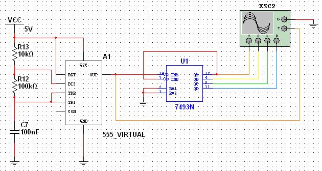
Digital Circuits
This tutorial explores a common digital concept using the NI Multisim software environment. It examines a four-bit counter that uses a 555 timer IC to generate the clock signal. This tutorial takes less than 30 minutes to complete and consists...

Astable Multivibrator I Circuit
In this multivibrator circuit, frequency and pulse width can be separately controlled by using steering diodes (1N914) and two potentiometers.
This multivibrator circuit utilizes steering diodes, specifically the 1N914 type, to enable independent control over both the frequency and pulse width...

Dual astable multivibrator
This dual astable multivibrator offers versatility not found in single timer circuits. The duty cycle can be adjusted from 5% to 95%. The two outputs generate two-phase clock signals, which are frequently required in digital systems. Additionally, it can be...

Starting Network for Astable Multivibrator
An astable multivibrator is a flip-flop that produces two unstable states (high and low), functioning as an oscillator.
An astable multivibrator is a fundamental electronic circuit that continuously switches between its two states without requiring any external triggering signals. This...
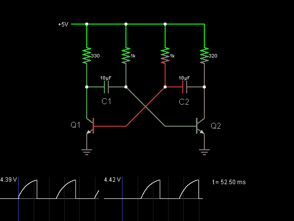
Astable Multivibrator (Oscillator)
This circuit functions as an astable multivibrator, also known as an oscillator. The two transistors are interconnected in a manner that allows the circuit to alternate between two states. In one state, the base of transistor Q1 is approximately one...

astable multivibrator
The astable multivibrator presented in Wikipedia and college materials is depicted on the left side of the image. In contrast, the schematic on the right side is sourced from an LTSpice example. The right schematic is incorrectly drawn, and the...

astable multivibrator
Two 47k ohm resistors, with alternative values ranging from 22k to 100k ohm, can be used. The value of these resistors affects the timing of the blinking; larger values result in slower blinking.
In a typical electronic circuit designed for blinking...

Astable Multivibrator Electronic
Function: to trigger a device or operate in free-running mode. Components: Battery, Charger, Battery Connector, Capacitor, Integrated Circuit (IC), Resistor VR1-10K, Resistor R1-1K, Resistor R2.
The described circuit functions either to trigger a connected device or to operate in a free-running...

Astable multivibrator-2 LED flashing circuit2N39043.7V
Many friends have requested an automatic on/off LED circuit or an LED flashing circuit. This post presents an astable multivibrator circuit designed for LED flashing. It is a simple astable multivibrator circuit utilizing two LEDs (specifically red LEDs) and two...