


The basic structure of the DA converter
#DA converter
#A/D converter
#parallel type
#median
#bit
#digital signal
#analog signal
#conversion
#circuit design

Description: An A/D converter circuit can be represented by a simplified schematic, which illustrates a parallel type A/D converter. The term "median" refers to the number of bits in the digital signal output. The figure displays four A/D converters utilizing five voltage comparators, with quantization levels of 24 and 16, corresponding to 16 quantization levels.
The parallel type A/D converter circuit operates by converting an analog signal into a digital representation through simultaneous comparisons. In this configuration, the circuit employs multiple voltage comparators to assess the input signal against predefined reference voltages. The number of bits determines the resolution of the output digital signal, where each bit corresponds to a quantization level.
In this specific design, four A/D converters are integrated, each contributing to the overall conversion process. The use of five voltage comparators allows for effective discrimination between the quantization levels, enhancing the accuracy of the conversion. The quantization levels mentioned, 24 and 16, indicate the potential output states that the analog input can be mapped to, with 16 distinct levels being a common standard for many applications.
This circuit design is particularly useful in applications requiring high-speed data acquisition and processing, where rapid conversion of analog signals to digital form is essential. The parallel nature of the circuit allows for simultaneous processing of multiple signals, significantly improving the throughput of data in systems such as digital oscilloscopes, data loggers, and various measurement instruments. The careful selection of voltage comparators and quantization levels plays a critical role in optimizing the performance and accuracy of the A/D conversion process.A/D converter circuit can be represented by a simplified circuit shown in Figure 4 is a (bit) parallel type A/D converter circuit, the so-called median is the number of bits in a digital signal output means. From the figure shows, four A/D converters use I5 voltage comparators. 4 quantization, namely 24 16, press l6 quantization levels.
The parallel type A/D converter circuit operates by converting an analog signal into a digital representation through simultaneous comparisons. In this configuration, the circuit employs multiple voltage comparators to assess the input signal against predefined reference voltages. The number of bits determines the resolution of the output digital signal, where each bit corresponds to a quantization level.
In this specific design, four A/D converters are integrated, each contributing to the overall conversion process. The use of five voltage comparators allows for effective discrimination between the quantization levels, enhancing the accuracy of the conversion. The quantization levels mentioned, 24 and 16, indicate the potential output states that the analog input can be mapped to, with 16 distinct levels being a common standard for many applications.
This circuit design is particularly useful in applications requiring high-speed data acquisition and processing, where rapid conversion of analog signals to digital form is essential. The parallel nature of the circuit allows for simultaneous processing of multiple signals, significantly improving the throughput of data in systems such as digital oscilloscopes, data loggers, and various measurement instruments. The careful selection of voltage comparators and quantization levels plays a critical role in optimizing the performance and accuracy of the A/D conversion process.A/D converter circuit can be represented by a simplified circuit shown in Figure 4 is a (bit) parallel type A/D converter circuit, the so-called median is the number of bits in a digital signal output means. From the figure shows, four A/D converters use I5 voltage comparators. 4 quantization, namely 24 16, press l6 quantization levels.

Cyclic A/D converter circuit
The cyclic converter is composed of a series of identical stages, each stage detecting the polarity of the input. The reference voltage, V_REF, is subtracted from the double entry, and the remaining value is processed if the polarity is correct....

A/D Converter with LT1018
The converter has a 60 ms conversion time, consuming 460 pA of current from a 5 V power supply, while maintaining an accuracy of 10 bits at 15 °C within a temperature range of 35 °C. A pulse applied to...
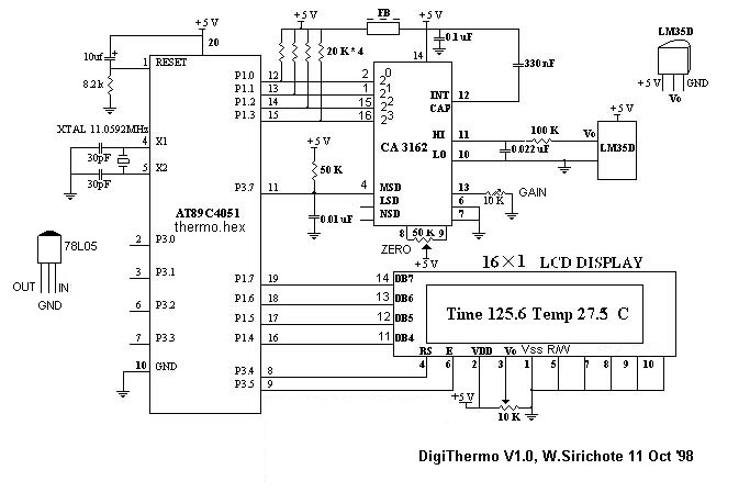
Cute Palm-Sized DigiThermo
The A/D converter utilizes a dual-slope integrator to achieve a sampling rate of 10 Hz. The digital output sent to the microcontroller (MCU) is multiplexed in a four-bit Binary-Coded Decimal (BCD) format, starting from the Most Significant Digit (MSD), followed...

a d converter
This is the preliminary draft of the pH to 1-Wire converter schematic, with some component values still pending. The original circuit operates on 12 VDC, but since the A/D converter IC requires a 5 VDC supply, the circuit needs to...

Simple A/D converter circuit with 2504
The time IO-bit conversion operates at 3.3 MHz with a clock signal. This converter utilizes a 2504 12-bit register in successive approximation mode, where the conversion signal for the short-cycle end is derived from the first bit utilized in the...

Audio AD converter circuit configuration
Audio A/D converter circuit configuration using the CS5333 chip, which is a high-performance 24-bit, 96 kHz stereo A/D converter commonly used in digital products. This circuit converts one or more audio signals into a digital signal for processing and storage.
The...

8-Channel A/D Converter For Pc Clones Circuit
An A/D converter by National Semiconductor (ADC0838) converts 0 to 5 V analog inputs into a digital data format. A 9 V battery is utilized. The converter connects to the pointer port connector through a 25-pin connector.
The ADC0838 is a...

A/D converter 16Bit with LCD and PIC18F2550
The analog to digital converter (ADC) is commonly required in most of the projects. Analog voltage measurement can be done using the ADC hardware built in together in a PIC. The picture below shows a simple setup for measuring the...

case stepper
Beige Bag Software has been offering affordable and innovative circuit design tools since 1990. B2 Spice provides schematics as well as analog, digital, and mixed-mode electronic circuit simulation. It integrates with EAGLE and CADSTAR PCB software.
B2 Spice is a powerful...