


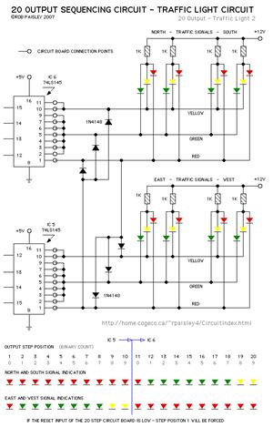
traffic light circuit diagram
#VHDL
#CPLD
#traffic light
#Altera MAX PLUS
#hardware description
#simulation
#programmable logic
#controller
#intersection control
#EDA software
Description: The current application involves the use of the VHDL hardware description language for designing a traffic light system controller circuit. This design is implemented within the Altera MAX PLUS EDA software environment, which facilitates compilation, simulation, and programming for CPLD devices to achieve effective traffic light system control. Keywords include EDA, VHDL, controller, and CPLD. EDA technology enhances electronic product design by allowing designers to modify programs directly, reducing the need for hardware support, shortening development cycles, and saving costs. Numerous methods exist for controlling intersection traffic signal systems, including standard logic devices, programmable logic controllers (PLC), and microcontrollers. However, these methods typically require hardware modifications for debugging, complicating the functional changes and system debugging processes. Consequently, EDA technology is now widely utilized in designing traffic signal system controllers using VHDL. The MAX PLUS integrated development environment is employed for simulation and programming of CPLD devices to complete system control. The design requirements for the traffic light system controller include a division between the controller and the controlled circuit. The controller manages the operation of the entire system by alternating commands for vehicles and pedestrians while receiving feedback signals to determine state transitions and output signals for system control. The intersection traffic light control system includes various traffic lights, such as red (R), yellow (Y), and green (G) for vehicular traffic, and red (RXR) and green (RXG) for pedestrian signals. The system operates based on preset timing intervals, with a timing model that includes transitions every 5 to 15 seconds. The controller's output is based on binary counts, and an external reference pulse signal is supplied. The system's operation is visually represented in an ASM chart, which reflects different states and timing transitions of the traffic signal system. The VHDL programming for the controller is developed according to this ASM chart and design requirements, culminating in a top-level file that is compiled and simulated in the MAX PLUS environment. Errors identified during compilation necessitate modifications until the program meets operational standards.
The traffic light system controller is designed to manage the flow of vehicles and pedestrians at an intersection efficiently. The architecture separates the controller from the controlled circuitry, allowing for modular design and flexibility in programming. The controller interprets input signals, which are active high, and generates output signals that dictate the state of the traffic lights. The design incorporates a timing mechanism that ensures traffic lights change states at predetermined intervals, enhancing safety and efficiency.
In the VHDL implementation, the controller's functionality is expressed through a series of state transitions, as outlined in the ASM chart. Each state corresponds to a specific configuration of the traffic lights, ensuring that vehicles and pedestrians receive appropriate signals based on real-time traffic conditions. The timing intervals are critical, as they determine how long each light remains active, thus influencing traffic flow and pedestrian safety.
The simulation process within the MAX PLUS environment allows for thorough testing of the design before deployment. It enables designers to verify that all components interact correctly and that the system adheres to the specified timing and logic requirements. Any errors detected during simulation must be addressed, ensuring that the final design is robust and reliable.
Overall, the integration of EDA technology and VHDL in the design of traffic light systems represents a significant advancement in electronic engineering, facilitating the creation of sophisticated control systems that are both efficient and adaptable to varying traffic conditions.The design of the current application of the wider selection of VHDL hardware description language to realize the intersection traffic light system controller hardware circuit description, in the Altera`s MAX PLUS EDA software platform environment through the compilation, simulation, and ed to the CPLD production of the device is programmed to ach ieve the traffic light system control process. Keywords: EDA; VHDL; controller; CPLD Introduction EDA technology is used in electronic product design, more advanced technology, can replace the design of electronic systems designers to complete most of the work, and can be modified directly from the program and system errors function without the need for hardware support, not only shorten the development cycle, but also significant cost savings by the electronic engineers of all ages. To achieve control of intersection traffic signal systems are many ways you can use the standard logic devices, programmable logic controller PLC, SCM and other programs to achieve.
However, the function of these control methods are required to modify and debug hardware support, to a certain extent, an increase of functional changes and system debugging difficulties. Therefore, the use of EDA in the design of technology, applications are now widely used in the VHDL hardware description language to realize the design of traffic signal system controller, using MAXPLUS comprehensive integrated development environment, simulation, and to the CPL D programmable logic device, complete Control of the system.
Traffic light system controller design requirements junction traffic light control system and other control systems, controllers and the controlled circuit is divided into two parts. Controller so that the whole system works by setting alternate command vehicles and pedestrians, traffic, and receiving controlled part of the feedback signal and determine the direction of state transition and output signals to control the whole system works.
Intersection traffic operation in accordance with the actual situation, in this system, set the system works as follows. Intersection traffic light control system of traffic lights the road things R (red), Y (yellow), G (green); things safe passage pedestrian lights: RXR (red), RXG (green).
North-south road with traffic lights: r1 (red), y1 (yellow), g1 (green); safe passage north-south pedestrian lights: rxr1 (red), rxg1 (green), all lights are lit high. Set the passage of time and 5s 15s conversion time of change model timing, the decision by the preset input is an integer cnt die 15 or die 5, the input logic is used to determine the count to cx 4 to 14, or cleared when cleared.
Clk is the second externally supplied reference pulse signal. x0, x1, x2, x3 is output by the controller, said four binary count of time. Figure 1 is a symbolic diagram of the system controller. Controller * controller ASM programming plans based on system design requirements, get the controller ASM chart shown in Figure 2. Here, all input signals are active high. The ASM chart reflects the different states of traffic signal systems and the duration of the conversion process.
* VHDL programming the controller of the system according to the ASM chart, combined with the design requirements of each module using VHDL programming language, and finally form a top-level file, MAX PLUS compilation and simulation environment to check the programmed is operating correctly. If an error occurs, you need to be modified until it get approved. It should be noted that, during the compilation process, the first program from the ground up, all the underlying programs are correct, can begin to compile top-level program.
This is because the top-level program is a summary of the underlying process, which is the underlying process linking the various modules, each module is equivalent to the function of gathering together to achieve the overall system con
The traffic light system controller is designed to manage the flow of vehicles and pedestrians at an intersection efficiently. The architecture separates the controller from the controlled circuitry, allowing for modular design and flexibility in programming. The controller interprets input signals, which are active high, and generates output signals that dictate the state of the traffic lights. The design incorporates a timing mechanism that ensures traffic lights change states at predetermined intervals, enhancing safety and efficiency.
In the VHDL implementation, the controller's functionality is expressed through a series of state transitions, as outlined in the ASM chart. Each state corresponds to a specific configuration of the traffic lights, ensuring that vehicles and pedestrians receive appropriate signals based on real-time traffic conditions. The timing intervals are critical, as they determine how long each light remains active, thus influencing traffic flow and pedestrian safety.
The simulation process within the MAX PLUS environment allows for thorough testing of the design before deployment. It enables designers to verify that all components interact correctly and that the system adheres to the specified timing and logic requirements. Any errors detected during simulation must be addressed, ensuring that the final design is robust and reliable.
Overall, the integration of EDA technology and VHDL in the design of traffic light systems represents a significant advancement in electronic engineering, facilitating the creation of sophisticated control systems that are both efficient and adaptable to varying traffic conditions.The design of the current application of the wider selection of VHDL hardware description language to realize the intersection traffic light system controller hardware circuit description, in the Altera`s MAX PLUS EDA software platform environment through the compilation, simulation, and ed to the CPLD production of the device is programmed to ach ieve the traffic light system control process. Keywords: EDA; VHDL; controller; CPLD Introduction EDA technology is used in electronic product design, more advanced technology, can replace the design of electronic systems designers to complete most of the work, and can be modified directly from the program and system errors function without the need for hardware support, not only shorten the development cycle, but also significant cost savings by the electronic engineers of all ages. To achieve control of intersection traffic signal systems are many ways you can use the standard logic devices, programmable logic controller PLC, SCM and other programs to achieve.
However, the function of these control methods are required to modify and debug hardware support, to a certain extent, an increase of functional changes and system debugging difficulties. Therefore, the use of EDA in the design of technology, applications are now widely used in the VHDL hardware description language to realize the design of traffic signal system controller, using MAXPLUS comprehensive integrated development environment, simulation, and to the CPL D programmable logic device, complete Control of the system.
Traffic light system controller design requirements junction traffic light control system and other control systems, controllers and the controlled circuit is divided into two parts. Controller so that the whole system works by setting alternate command vehicles and pedestrians, traffic, and receiving controlled part of the feedback signal and determine the direction of state transition and output signals to control the whole system works.
Intersection traffic operation in accordance with the actual situation, in this system, set the system works as follows. Intersection traffic light control system of traffic lights the road things R (red), Y (yellow), G (green); things safe passage pedestrian lights: RXR (red), RXG (green).
North-south road with traffic lights: r1 (red), y1 (yellow), g1 (green); safe passage north-south pedestrian lights: rxr1 (red), rxg1 (green), all lights are lit high. Set the passage of time and 5s 15s conversion time of change model timing, the decision by the preset input is an integer cnt die 15 or die 5, the input logic is used to determine the count to cx 4 to 14, or cleared when cleared.
Clk is the second externally supplied reference pulse signal. x0, x1, x2, x3 is output by the controller, said four binary count of time. Figure 1 is a symbolic diagram of the system controller. Controller * controller ASM programming plans based on system design requirements, get the controller ASM chart shown in Figure 2. Here, all input signals are active high. The ASM chart reflects the different states of traffic signal systems and the duration of the conversion process.
* VHDL programming the controller of the system according to the ASM chart, combined with the design requirements of each module using VHDL programming language, and finally form a top-level file, MAX PLUS compilation and simulation environment to check the programmed is operating correctly. If an error occurs, you need to be modified until it get approved. It should be noted that, during the compilation process, the first program from the ground up, all the underlying programs are correct, can begin to compile top-level program.
This is because the top-level program is a summary of the underlying process, which is the underlying process linking the various modules, each module is equivalent to the function of gathering together to achieve the overall system con

SuperSpice
SuperSpice's philosophy is centered around the edit schematic, run simulation, view waveforms, probe signals, view waveforms, edit schematic cycle. All key issues have been automated. You can effortlessly modify the schematic, rerun and inspect new waveforms without having to reload...
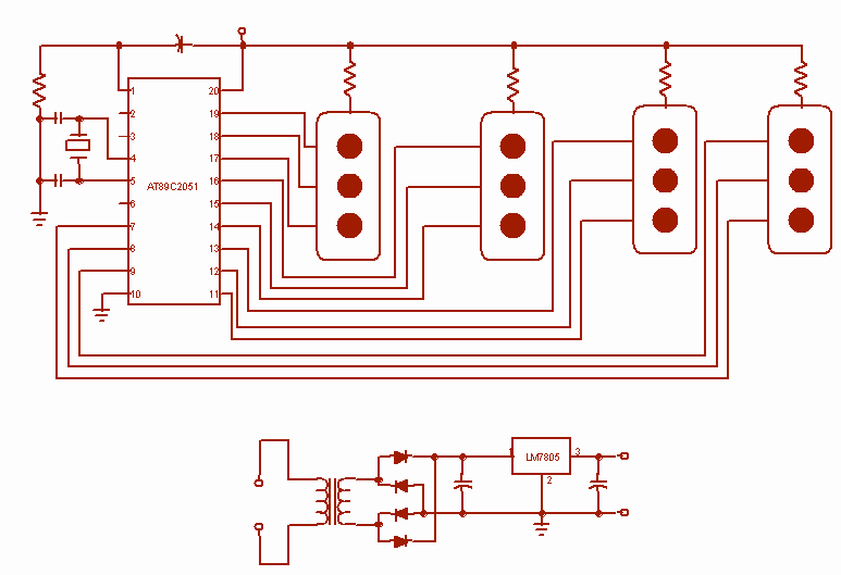
Traffic Light Controller
Four way Traffic light controller which Has Red, Yellow and Green LEDS. It uses the AT89C2051.
The four-way traffic light controller is an essential electronic system designed to manage traffic flow at intersections by controlling the operation of Red, Yellow, and...

traffic simple
The controller is entirely hardware-based and provides the typical sequencing for a standard three-light traffic signal. This traffic light controller/sequencer was constructed during the initial learning phase of electronics. Although it may be considered crude and unattractive, it effectively served...

controller
As summer approaches, many individuals focus on staying cool during hot days. For some, this means turning on the air conditioner and enjoying a cold beverage. However, it is essential to consider how to maintain the temperature of radio equipment...

CPLD Programming
This programming interface circuit transmits programming signals from a USB cable directly to an FPGA chip via a standardized 10-pin interface. Typically, only 4 or 5 signal pins are utilized, excluding GND and any unused pins from the 10-pin ribbon...

Circuit Magic
Circuit Magic is an electrical circuits simulation program specifically designed for students teaching basics electronics, electrical laws & circuit theory. Unlike many electronic circuit analyzers, Circuit Magic can analyze circuits like a man. Circuits are simulated step by step, using...

Few words about CPLD
The project involves the use of a Lattice isp2032VE110LT144 programmable logic chip, with a focus on integrating an LCD screen module. The development process included using MS Visual Basic for LCD control and the ispLever Navigator software for programming the...

Programmable logic devices (CPLD)
Complex programmable logic devices (CPLDs) contain the building blocks for hundreds of 7400-series logic ICs. Complete circuits can be designed on a PC and then uploaded to a CPLD for instant implementation.
CPLDs are integrated circuits that provide a versatile solution...

io port programing chalange
This program is a simple Traffic Light Controller. Between the start time and end time, the system controls a traffic light with pedestrian self-service. Outside of this time range, the yellow caution lamp is blinking. The commands include displaying times,...