


Tug of War (Verilog)
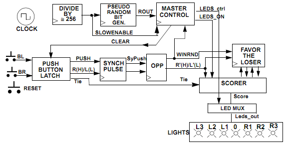
Description: Tug Of War is a game developed on an FPGA. The digital circuit was designed using Verilog and operates as a Finite State Machine (FSM).
The Tug Of War game implemented on an FPGA utilizes a Finite State Machine (FSM) architecture to control the game logic and state transitions. The FSM is designed to manage different states of the game, such as initializing, waiting for player input, processing game actions, and determining the winner.
In the FSM, each state corresponds to a specific phase of the game. For instance, the initial state may set up the game parameters and prepare the display for player interaction. The subsequent states handle player inputs, such as button presses or joystick movements, which are captured through the FPGA's input pins. The FSM processes these inputs to update the game state, which may involve changing scores, updating the game display, or transitioning to a win/lose state.
The design includes various combinational and sequential logic components. Combinational logic is used to determine the next state based on the current state and inputs, while sequential logic is responsible for maintaining the current state of the FSM. The Verilog code effectively describes these components, ensuring that the timing and sequencing of state transitions are synchronized with the clock signal provided by the FPGA.
Furthermore, the output of the FSM can interface with visual indicators, such as LEDs or a display module, to provide real-time feedback to players. Additional features may include sound effects or score tracking, which can be integrated into the design by expanding the FSM states and incorporating additional hardware components.
Overall, the Tug Of War game exemplifies the application of digital design principles, showcasing how an FSM can be utilized within an FPGA to create an interactive gaming experience.Tug Of War is a game that I made on an FPGA. The digital circuit was created using Verilog. It is a FSM (Finite State Machine).
The Tug Of War game implemented on an FPGA utilizes a Finite State Machine (FSM) architecture to control the game logic and state transitions. The FSM is designed to manage different states of the game, such as initializing, waiting for player input, processing game actions, and determining the winner.
In the FSM, each state corresponds to a specific phase of the game. For instance, the initial state may set up the game parameters and prepare the display for player interaction. The subsequent states handle player inputs, such as button presses or joystick movements, which are captured through the FPGA's input pins. The FSM processes these inputs to update the game state, which may involve changing scores, updating the game display, or transitioning to a win/lose state.
The design includes various combinational and sequential logic components. Combinational logic is used to determine the next state based on the current state and inputs, while sequential logic is responsible for maintaining the current state of the FSM. The Verilog code effectively describes these components, ensuring that the timing and sequencing of state transitions are synchronized with the clock signal provided by the FPGA.
Furthermore, the output of the FSM can interface with visual indicators, such as LEDs or a display module, to provide real-time feedback to players. Additional features may include sound effects or score tracking, which can be integrated into the design by expanding the FSM states and incorporating additional hardware components.
Overall, the Tug Of War game exemplifies the application of digital design principles, showcasing how an FSM can be utilized within an FPGA to create an interactive gaming experience.Tug Of War is a game that I made on an FPGA. The digital circuit was created using Verilog. It is a FSM (Finite State Machine).

FPGA / CPLD 16x2 LCD Interface Circuit
The schematic for this project is a modified version of the CPLD development board schematic. Several new components have been added for this project, and the completed schematic is presented below. The primary components in the schematic include the CPLD...
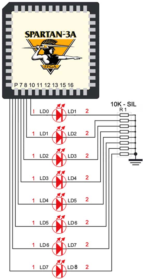
how to interface led with spartan 3an
The Spartan-3an board features eight LEDs connected to FPGA I/O pins. The cathode of each LED is connected to ground through a 330-ohm resistor. To illuminate a specific LED, the corresponding FPGA control signal must be set to High.
The Spartan-3an...
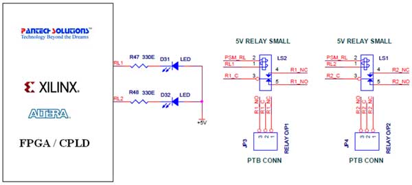
relay interfacing with fpga universal development board
The Universal Development Board features external 5V relay interfacing, as illustrated in the accompanying figure. The ULN2803 is utilized as a driver for FPGA I/O lines, with the driver outputs connected to the relay modules. A PTB connector is provided...

Steady Hands Game Project
A "Steady Hands Game" was developed to meet the requirement for a cub-scout event. Initially prototyped on a homework board, a more permanent version of the game was created for educational purposes. The final version features a wand (black) that...
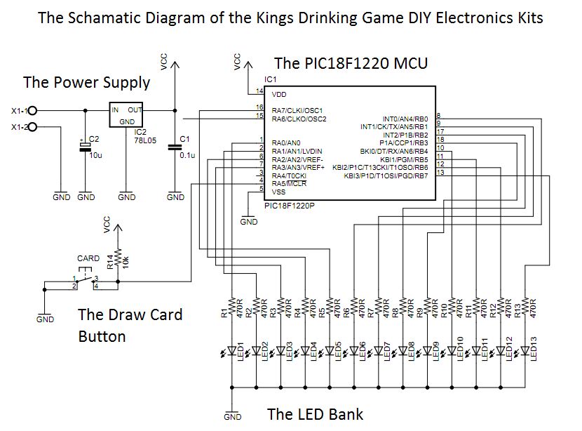
The Electronic Kings drinking game circuit!
This circuit was designed approximately four months ago and has been developed into a kit for others to use.
The circuit in question appears to be a well-thought-out design that has been packaged into a kit format, making it accessible for...

development and evaluation for FPGA based systems
The System Monitor feature discussed in this article was successfully utilized by Avalon Microelectronics in two Virtex-5 FPGAs (XC5VLX330T) during their development. They encountered an unusual issue where the development board would shut down while the FPGAs were executing certain...

HANGMAN schematic
Everybody likes re-discovering something they did years ago. Here's a game we all played at school. Possibly under the name of HANG THE BUTCHER. The game is quite simple. One player thinks of a word and writes down the number...

Who is first
This circuit is designed for use in a question-and-answer party game. The first button pressed ionizes a neon bulb, causing the DC voltage across the parallel-connected neon bulbs (representing other contestants) to drop below the ionization threshold, thereby clearly identifying...

Reference designs for Series 1 FPGA Boards
ZTEX USB-FPGA Boards require three different voltages: 1.2V, 2.5V-2.6V, and 3.3V, which must be supplied externally. This can be achieved using Power Supply Modules, Experimental Boards, or a user-specific design. To facilitate development in the latter scenario, three reference power...