



Mark 2 Memory circuit
The memory part of my Mark 2 system is extremely simple. There are two 32K SRAM chips (actually FRAM because I had them lying around, but there isn`t any signif...

16 Step Sequencer Quantized Vari-Clock Module
A mechanism by which a normal pot could be used as a digitized pot since I need each pot`s setting to be converted to a number between 0 and 15. I use that info...
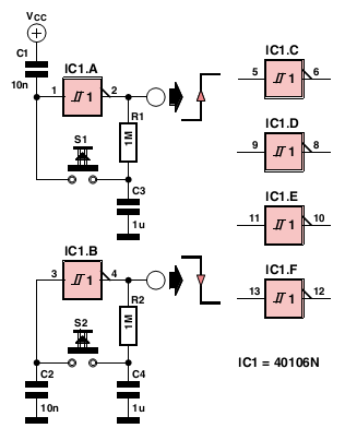
simple six way switch using ic1 40106n
...
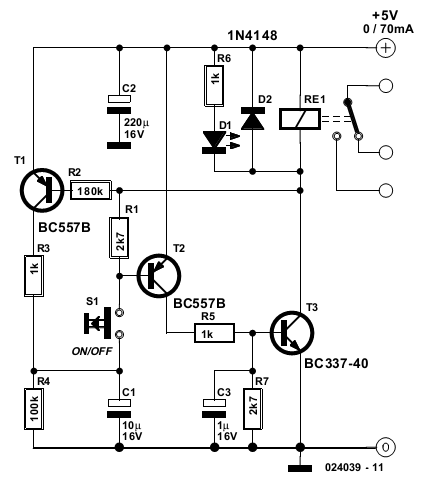
pushbutton switch circuit
...
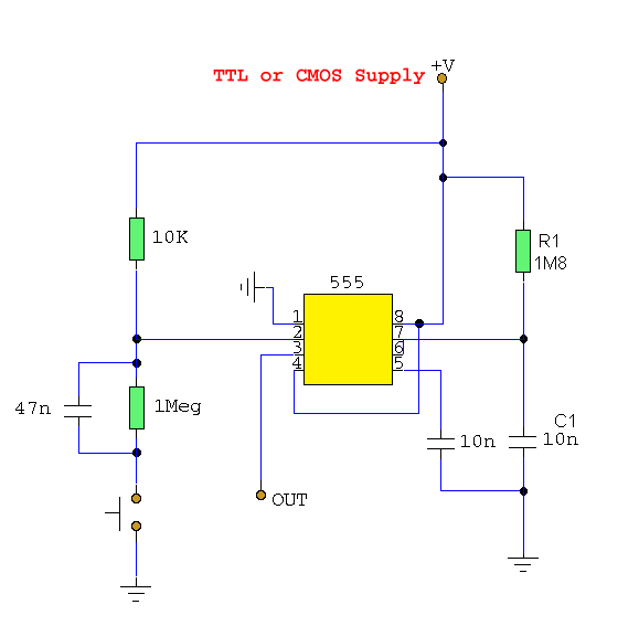
push button switch de bouncer
...

digital switching system
This circuit can control any one out of 16 devices with the help of two push-to-on switches. An up/down counter acts as a master-controller for the system. A vi...
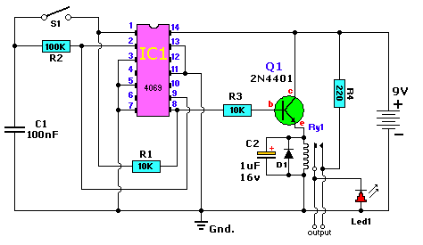
alternating on off switch with ic 4069
...

digital dice with 7 segment display
...
PSIM Training CD-ROMs
The counter must be programmed as part of a batch-counting operation to sort parts automatically for quality control. The counter is installed to divert 1 part ...

video sequencer using analog multiplexers
Here is another example of using a CD4051 multiplexer, or more accurately a pair of CD4051s in parallel. I had lifted much of the core logic and circuits from D...

MikroC Pro for PIC driver routine for 74HC595 based serial LCD interface
Library routines for 3-wire LCD interface based on 74HC595 shift register. More details are provided in the attached ReadMe document or posted at Do you want to...

Electromechanical relay logic
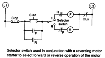
In ladder logic symbolism, an electromechanical relay coil is shown as a circle, and the contact(s) actuated by the coil as two parallel lines, almost like a ca...

Encoders and decoders
...

7-segment display
This experiment is more of an introduction to the 4511 decoder/display driver IC than it is a lesson in how to "build up" a digital function from lower-level co...

LED sequencer
The model 4017 integrated circuit is a CMOS counter with ten output terminals. One of these ten terminals will be in a "high" state at any given time, with all ...

NAND gate S-R flip-flop
Although the parts list calls for a ten-segment LED unit, the illustration shows two individual LEDs being used instead. This is due to lack of room on my bread...

Basic gate function
To begin, connect a single NAND gate to two input switches and one LED, as shown. At first, the use of an 8-position switch and a 10-segment LED bargraph may se...
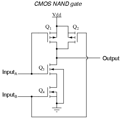
CMOS gate circuitry
...

One Of Nine Sequencer
This novel circuit uses a flashing LED as the clock input for a 4017 decade counter. Typical flashing LEDs (eg, DSE cat Z-4044) flash at about 2Hz so the output...

Logic Probe With Sound
This logic probe can be selected to operate on TTL or CMOS logic levels, depending on switch S1. A string of resistors associated with switch S1 sets the thresh...