


tate ambient power module
#ambient power
#antenna
#grounding
#energy harvesting
#coil
#power generation
#circuit design
#experimental

Description: A notable observation is that connecting both the circuit ground and the antenna to separate ground points significantly enhances power output compared to using a standard antenna and coil setup. A coil similar to one described on an ambient power webpage was constructed, but it did not yield satisfactory results. Testing revealed that power output is closely related to the size of the capacitors and the quality of grounding for both the antenna and circuit. A metal stake driven into the ground provides a reasonable grounding solution, but maximizing the surface area of metal in contact with the ground yields better results. For instance, burying aluminum foil sheets in the ground proved effective. Currently, the circuit uses the house ground and a metal fence for the antenna ground, which has shown promising performance. The circuit employs 470uF capacitors and IN60 germanium diodes, chosen for their low voltage drop, allowing for greater current collection compared to 47uF capacitors. Additionally, the original 0.2uF capacitors were replaced with 47uF capacitors, with plans to upgrade to even larger capacitor values. However, the high cost of 50-500 farad capacitors, priced at over $1000 each, poses a challenge for acquiring the necessary quantity. The circuit, previously exhibiting issues with the diode, has been repaired and is functioning well. It has been tested both through simulation and practically, with current and voltage measurements provided, along with a load (a light bulb). Despite current collection being limited, the design has achieved up to 27 volts. Presently, the circuit operates as a night light, although it is excessively bright for that purpose, utilizing an 8000 mcd white LED. Further improvements are anticipated to enable powering additional devices beyond just an LED.
The described circuit setup demonstrates an innovative approach to enhancing power generation through effective grounding and component selection. The dual grounding technique, which involves connecting the circuit ground and antenna ground to separate earth points, is critical for optimizing performance. This method aids in reducing ground loop interference and can improve the overall efficiency of the power collection system.
In terms of component selection, the use of 470uF capacitors allows for increased energy storage and improves the circuit's ability to handle transient loads. The IN60 germanium diodes are particularly advantageous due to their low forward voltage drop, which minimizes power loss and enhances the overall efficiency of the circuit. The decision to replace smaller capacitors with larger values indicates a strategic approach to maximizing the circuit's energy storage capabilities.
The experimental grounding techniques, such as burying aluminum foil sheets, reflect a practical understanding of the importance of grounding in electronic circuits. The larger the surface area of the grounding material, the more effective the grounding becomes, leading to improved circuit performance.
The circuit's ability to achieve 27 volts is notable, especially for a design focused on low-power applications. Although the output is currently utilized for a bright LED, the potential for further enhancements could allow for the powering of more complex devices. This adaptability showcases the circuit's versatility and the engineer's commitment to continual improvement.
Overall, this circuit exemplifies a hands-on approach to electronic design, emphasizing the importance of grounding, component selection, and iterative testing. The results achieved thus far provide a solid foundation for future advancements in power generation and circuit efficiency.Hey another cool thing I found is that if you earth both the earth of the circuit to ground and the other end of the antenna to a separate ground, you increase the power dramaticaly, compared to using a normal antenna and coil. I made a similar coil to the one mentioned on the ambient power web page but it didn`t help. I have tested and found that the power output is greatly related to how large your capacitors are and how well grounded your antenna and circuit grounds are. A metal stake shoved in the ground provides a reasonable ground. But I found that it is much better to get the largest surface area of metal in contact with the ground as possible.
I even tryed digging a hole and planting aluminium foil sheets in the ground. That worked quite well. At the moment I am using the earth of the house for the circuit earth and a metal fence for the antenna earth. This is working great. So far I am using 470uF capacitors and IN60 germanium diodes as they have a low voltage drop and the capacitors collect more current compared to 47uF.
I also replaced the 0. 2uF capacitors in the original diagram to 47uF capacitors aswell. I also intend to replace them all to much higher capacitor values. Although the mentioned 50-500 farred capacitors on the web site cost a fortune as each one costs $1000+ each and I would need 12 of them. The first circuit showen on the web page that had the problem with the diode, I fixed and is running quite well.
I have included a picture of the fixed circuit in this e-mail as an attatchment if you would like to have a look at it. If you have a look at the circuit you will see that it is the diode in red that has been fixed. This circuit has been test run with a computer program as well as practicaly. An example output of current and voltage measurements is also included along with a load (The light bulb).
Unfortunatly practicly I havn`t been able to collect that much current yet. Although I am working on it. But I have been able to get up to 27 volts with this design. At the moment the circuit runs nicely as a night light although it is probably too bright to be used as I night light. I use an 8000 mcd white LED which is definatly bright. But I know that I will inprove the circuit further and will hopefully be able to power more than just an LED.
The described circuit setup demonstrates an innovative approach to enhancing power generation through effective grounding and component selection. The dual grounding technique, which involves connecting the circuit ground and antenna ground to separate earth points, is critical for optimizing performance. This method aids in reducing ground loop interference and can improve the overall efficiency of the power collection system.
In terms of component selection, the use of 470uF capacitors allows for increased energy storage and improves the circuit's ability to handle transient loads. The IN60 germanium diodes are particularly advantageous due to their low forward voltage drop, which minimizes power loss and enhances the overall efficiency of the circuit. The decision to replace smaller capacitors with larger values indicates a strategic approach to maximizing the circuit's energy storage capabilities.
The experimental grounding techniques, such as burying aluminum foil sheets, reflect a practical understanding of the importance of grounding in electronic circuits. The larger the surface area of the grounding material, the more effective the grounding becomes, leading to improved circuit performance.
The circuit's ability to achieve 27 volts is notable, especially for a design focused on low-power applications. Although the output is currently utilized for a bright LED, the potential for further enhancements could allow for the powering of more complex devices. This adaptability showcases the circuit's versatility and the engineer's commitment to continual improvement.
Overall, this circuit exemplifies a hands-on approach to electronic design, emphasizing the importance of grounding, component selection, and iterative testing. The results achieved thus far provide a solid foundation for future advancements in power generation and circuit efficiency.Hey another cool thing I found is that if you earth both the earth of the circuit to ground and the other end of the antenna to a separate ground, you increase the power dramaticaly, compared to using a normal antenna and coil. I made a similar coil to the one mentioned on the ambient power web page but it didn`t help. I have tested and found that the power output is greatly related to how large your capacitors are and how well grounded your antenna and circuit grounds are. A metal stake shoved in the ground provides a reasonable ground. But I found that it is much better to get the largest surface area of metal in contact with the ground as possible.
I even tryed digging a hole and planting aluminium foil sheets in the ground. That worked quite well. At the moment I am using the earth of the house for the circuit earth and a metal fence for the antenna earth. This is working great. So far I am using 470uF capacitors and IN60 germanium diodes as they have a low voltage drop and the capacitors collect more current compared to 47uF.
I also replaced the 0. 2uF capacitors in the original diagram to 47uF capacitors aswell. I also intend to replace them all to much higher capacitor values. Although the mentioned 50-500 farred capacitors on the web site cost a fortune as each one costs $1000+ each and I would need 12 of them. The first circuit showen on the web page that had the problem with the diode, I fixed and is running quite well.
I have included a picture of the fixed circuit in this e-mail as an attatchment if you would like to have a look at it. If you have a look at the circuit you will see that it is the diode in red that has been fixed. This circuit has been test run with a computer program as well as practicaly. An example output of current and voltage measurements is also included along with a load (The light bulb).
Unfortunatly practicly I havn`t been able to collect that much current yet. Although I am working on it. But I have been able to get up to 27 volts with this design. At the moment the circuit runs nicely as a night light although it is probably too bright to be used as I night light. I use an 8000 mcd white LED which is definatly bright. But I know that I will inprove the circuit further and will hopefully be able to power more than just an LED.

Field circuit diagram of the needle
The antenna consists of approximately 20 cm of insulation made from strands, which are glued together inside a small plastic box. An RF current is processed through two diode rectifiers, and a 10k potentiometer is connected to the pin field....
wave antenna circuit
The circuit illustrated here demonstrates that, despite advancements in components and technology, it remains possible to design effective and intriguing circuits. This design utilizes two well-known transistors, the BF256C and the BF494. Along with the necessary resistors and capacitors, these...

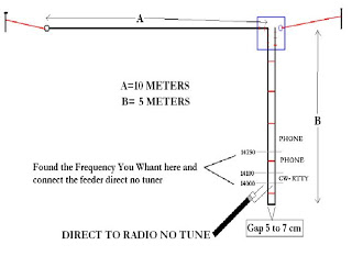
Ground pole & 2-Half-Wave Dipole Antenna
This Antenna is most widely used all over the world. For example, when you see a police car it has a transmitter with Ground Pole Antenna. The body of the car serves as ground. It accepts load from a 50-ohm...

The K9AY receiving loop antenna
A K9AY antenna system and controller has been designed with the intention of creating a more effective unit at a lower cost compared to commercially available versions. The K9AY antenna features a steerable null, maintaining a gain close to unity,...

case stepper
Beige Bag Software has been offering affordable and innovative circuit design tools since 1990. B2 Spice provides schematics as well as analog, digital, and mixed-mode electronic circuit simulation. It integrates with EAGLE and CADSTAR PCB software.
B2 Spice is a powerful...

Good vibrations for energy harvesting
A wide range of low-power industrial sensors and controllers are turning to alternative sources of energy as the primary or supplemental means of supplying power. Ideally, such harvested energy will eliminate the need for wired power or batteries altogether. Transducers...

Wideband Active Antenna Circuit
A whip antenna measuring between 30 to 50 cm is capable of receiving signals from 10 MHz to over 220 MHz. The circuit incorporates a BF981 dual-gate MOSFET (T1), which offers low noise characteristics, high input impedance, and enhanced performance.
The...

Q-Multiplying Loop Antenna
This circuit is designed to be used in conjunction with the standard 4 foot square loop used in MW for long distance reception.
The circuit described is intended for use with a 4-foot square loop antenna, which is a common choice...
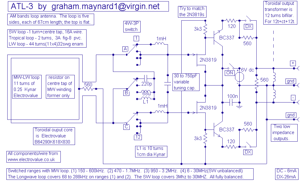
ATL-3 Loop Antenna
This antenna is the result of long term development and user feedback. All ATL-3 loop windings are centre tapped and balanced w.r.t. their amplifier/receiver chassis ground, and therefore electric field interference pick up tends to self cancel. Magnetic noise fields,...