


Tesla's Energy Reciever
#free-energy
#radiant energy
#cosmic rays
#Tesla
#patent
#negative electricity
#receiver
#solar
#wireless power

Description: Tesla's free-energy receiver was patented in 1901 as An Apparatus for the Utilization of Radiant Energy. The patent refers to "the Sun, as well as other sources of radiant energy, like cosmic rays." That the device works at night is explained in terms of the night-time availability of cosmic rays. Tesla also refers to the ground as "a vast reservoir of negative electricity." More: Tesla was fascinated by radiant energy and its free-energy possibilities. He called the Crooke's radiometer (a device which has vanes that spin in a vacuum when exposed to radiant energy) "a beautiful invention." He believed that it would become possible to harness energy directly by "connecting to the very wheelwork of nature." His free-energy receiver is as close as he ever came to such a device in his patented work.
But, on his 76th birthday, at the ritual press conference, Tesla (who was without the financial wherewithal to patent but went on inventing in his head) announced a "cosmic-ray motor." When asked if it was more powerful than the Crooke's radiometer, he answered, "thousands of times more powerful."
How it works
From the electric Potential that exists between the elevated plate (plus) and the ground (minus), energy builds in the capacitor, and, after "a suitable time interval," the accumulated energy will "manifest itself in a powerful discharge" which can do work. The capacitor, says Tesla, should be "of considerable electrostatic capacity," and its dielectric made of "the best quality mica,' for it has to withstand potentials that could rupture a weaker dielectric.
Tesla gives various options for the switching device. One is a rotary switch that resembles a Tesla circuit controller. Another is an electrostatic device consisting of two very light, membranous conductors suspended in a vacuum. These sense the energy build-up in the capacitor, one going positive, the other negative, and, at a certain charge level, are attracted, touch, and thus fire the capacitor. Tesla also mentions another switching device consisting of a minute air gap or weak dielectric film which breaks down suddenly when a certain potential is reached.
The above is about all the technical detail you get in the patent. Although I've seen a few cursory references to Tesla's invention in my sampling of the literature of free-energy, I am not aware of any attempts to verify it experimentally.
The Tesla free-energy receiver operates on the principles of electrostatics and radiant energy collection. The core component is a capacitor designed to accumulate electric charge through the influence of ambient radiant energy, including cosmic rays and solar radiation. The elevated plate of the capacitor serves as the positive terminal, while the ground acts as a negative terminal, creating a potential difference that facilitates energy storage.
The capacitor must possess significant electrostatic capacity, with a dielectric material of high quality, such as mica, to withstand the high voltage levels expected during operation. The dielectric is crucial as it prevents dielectric breakdown, which could lead to catastrophic failure of the capacitor.
For the energy discharge mechanism, Tesla proposed several switching devices. The rotary switch operates similarly to traditional circuit controllers, allowing for controlled energy release. The electrostatic switch, comprising lightweight conductors in a vacuum, relies on the principles of electrostatic attraction. As the capacitor charges, one conductor becomes positively charged while the other becomes negatively charged. Upon reaching a predetermined voltage, the two conductors attract, making contact and triggering the capacitor's discharge.
Another switching option involves a dielectric film with a specific breakdown voltage. When the voltage across this film exceeds its threshold, it rapidly fails, allowing the stored energy in the capacitor to be released in a sudden discharge. This rapid release can drive mechanical loads or power electrical devices, demonstrating the potential of Tesla's free-energy receiver.
The schematic would include the capacitor connected to the elevated plate and ground, with the various switching devices illustrated to show their configurations. Overall, Tesla’s design reflects a pioneering approach to harnessing energy from the environment, emphasizing the need for high-quality materials and innovative switching mechanisms to effectively utilize radiant energy.Tesla's free-energy receiver was patented in 1901 as An Apparatus for the Utilization of Radiant Energy. The patent refers to "the Sun, as well as other sources of radiant energy, like cosmic rays." That the device works at night is explained in terms of the night-time availability of cosmic rays.
Tesla also refers to the ground as "a vast reservoir of negative electricity." Tesla was fascinated by radiant energy and its free-energy possibilities. He called the Crooke's radiometer (a device which has vanes that spin in a vacuum when exposed to radiant energy) "a beautiful invention." He believed that it would become possible to harness energy directly by "connecting to the very wheelwork of nature." His free-energy receiver is as close as he ever came to such a device in his patented work. But, on his 76th birthday, at the ritual press conference, Tesla (who was without the financial wherewithal to patent but went on inventing in his head) announced a "cosmic-ray motor." When asked if it was more powerful than the Crooke's radiometer, he answered, "thousands of times more powerful." How it works From the electric Potential that exists between the elevated plate (plus) and the ground (minus), energy builds in the capacitor, and, after "a suitable time interval," the accumulated energy will "manifest itself in a powerful discharge" which can do work.
The capacitor, says Tesla, should be "of considerable electrostatic capacity," and its dielectric made of "the best quality mica,' for it has to withstand potentials that could rupture a weaker dielectric. Tesla gives various options for the switching device. One is a rotary switch that resembles a Tesla circuit controller. Another is an electrostatic device consisting of two very light, membranous conductors suspended in a vacuum.
These sense the energy build-up in the capacitor, one going positive, the other negative, and, at a certain charge level, are attracted, touch, and thus fire the capacitor. Tesla also mentions another switching device consisting of a minute air gap or weak dielectric film which breaks down suddenly when a certain potential is reached.
The above is about all the technical detail you get in the patent. Although I've seen a few cursory references to Tesla's invention in my sampling of the literature of free-energy, I am not aware of any attempts to verify it experimentally.
But, on his 76th birthday, at the ritual press conference, Tesla (who was without the financial wherewithal to patent but went on inventing in his head) announced a "cosmic-ray motor." When asked if it was more powerful than the Crooke's radiometer, he answered, "thousands of times more powerful."
How it works
From the electric Potential that exists between the elevated plate (plus) and the ground (minus), energy builds in the capacitor, and, after "a suitable time interval," the accumulated energy will "manifest itself in a powerful discharge" which can do work. The capacitor, says Tesla, should be "of considerable electrostatic capacity," and its dielectric made of "the best quality mica,' for it has to withstand potentials that could rupture a weaker dielectric.
Tesla gives various options for the switching device. One is a rotary switch that resembles a Tesla circuit controller. Another is an electrostatic device consisting of two very light, membranous conductors suspended in a vacuum. These sense the energy build-up in the capacitor, one going positive, the other negative, and, at a certain charge level, are attracted, touch, and thus fire the capacitor. Tesla also mentions another switching device consisting of a minute air gap or weak dielectric film which breaks down suddenly when a certain potential is reached.
The above is about all the technical detail you get in the patent. Although I've seen a few cursory references to Tesla's invention in my sampling of the literature of free-energy, I am not aware of any attempts to verify it experimentally.
The Tesla free-energy receiver operates on the principles of electrostatics and radiant energy collection. The core component is a capacitor designed to accumulate electric charge through the influence of ambient radiant energy, including cosmic rays and solar radiation. The elevated plate of the capacitor serves as the positive terminal, while the ground acts as a negative terminal, creating a potential difference that facilitates energy storage.
The capacitor must possess significant electrostatic capacity, with a dielectric material of high quality, such as mica, to withstand the high voltage levels expected during operation. The dielectric is crucial as it prevents dielectric breakdown, which could lead to catastrophic failure of the capacitor.
For the energy discharge mechanism, Tesla proposed several switching devices. The rotary switch operates similarly to traditional circuit controllers, allowing for controlled energy release. The electrostatic switch, comprising lightweight conductors in a vacuum, relies on the principles of electrostatic attraction. As the capacitor charges, one conductor becomes positively charged while the other becomes negatively charged. Upon reaching a predetermined voltage, the two conductors attract, making contact and triggering the capacitor's discharge.
Another switching option involves a dielectric film with a specific breakdown voltage. When the voltage across this film exceeds its threshold, it rapidly fails, allowing the stored energy in the capacitor to be released in a sudden discharge. This rapid release can drive mechanical loads or power electrical devices, demonstrating the potential of Tesla's free-energy receiver.
The schematic would include the capacitor connected to the elevated plate and ground, with the various switching devices illustrated to show their configurations. Overall, Tesla’s design reflects a pioneering approach to harnessing energy from the environment, emphasizing the need for high-quality materials and innovative switching mechanisms to effectively utilize radiant energy.Tesla's free-energy receiver was patented in 1901 as An Apparatus for the Utilization of Radiant Energy. The patent refers to "the Sun, as well as other sources of radiant energy, like cosmic rays." That the device works at night is explained in terms of the night-time availability of cosmic rays.
Tesla also refers to the ground as "a vast reservoir of negative electricity." Tesla was fascinated by radiant energy and its free-energy possibilities. He called the Crooke's radiometer (a device which has vanes that spin in a vacuum when exposed to radiant energy) "a beautiful invention." He believed that it would become possible to harness energy directly by "connecting to the very wheelwork of nature." His free-energy receiver is as close as he ever came to such a device in his patented work. But, on his 76th birthday, at the ritual press conference, Tesla (who was without the financial wherewithal to patent but went on inventing in his head) announced a "cosmic-ray motor." When asked if it was more powerful than the Crooke's radiometer, he answered, "thousands of times more powerful." How it works From the electric Potential that exists between the elevated plate (plus) and the ground (minus), energy builds in the capacitor, and, after "a suitable time interval," the accumulated energy will "manifest itself in a powerful discharge" which can do work.
The capacitor, says Tesla, should be "of considerable electrostatic capacity," and its dielectric made of "the best quality mica,' for it has to withstand potentials that could rupture a weaker dielectric. Tesla gives various options for the switching device. One is a rotary switch that resembles a Tesla circuit controller. Another is an electrostatic device consisting of two very light, membranous conductors suspended in a vacuum.
These sense the energy build-up in the capacitor, one going positive, the other negative, and, at a certain charge level, are attracted, touch, and thus fire the capacitor. Tesla also mentions another switching device consisting of a minute air gap or weak dielectric film which breaks down suddenly when a certain potential is reached.
The above is about all the technical detail you get in the patent. Although I've seen a few cursory references to Tesla's invention in my sampling of the literature of free-energy, I am not aware of any attempts to verify it experimentally.

automatic solar garden light circuit
Schematic of an automatic solar garden light circuit with 10 super bright white LEDs that will automatically activate at night.
The automatic solar garden light circuit is designed to harness solar energy for illumination purposes during nighttime. The circuit typically consists...

SOLAR_POWER_OVERCHARGE_PROTECTION
A voltage regulator is connected across the solar cell to prevent damage to the storage battery due to overcharging. A series diode prevents the array from discharging the battery during hours of darkness. The regulator does not draw power from...

mobile phone charger powered solar cell
A mobile phone charger powered by a solar cell power supply is described. This system utilizes a dual comparator circuit that connects the solar panel to the battery when the voltage at the battery terminal is low and disconnects it...
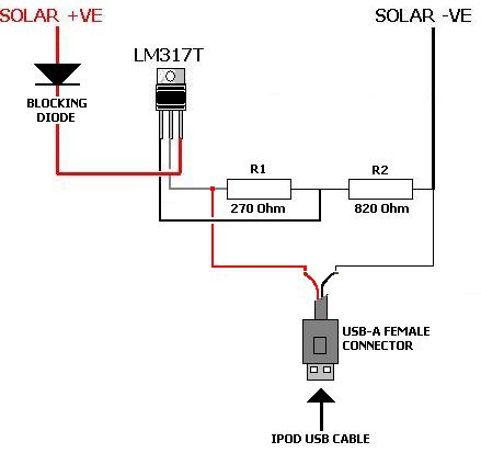
Solar iPod Charger
A solar charger for an iPod is no more difficult than creating a solar battery charger. Built-in iPod batteries operate at 3.7 Volts, with capacity (measured in mAh) varying by iPod model—e.g., 1,200mAh for a 2nd Gen, 850mAh for a...

Automatic Solar Garden Lights with LEDs
Efficient automatic solar garden lights circuit with minimal components. The advantage is that it operates completely automatically, with the solar panel serving as a light detector.
The efficient automatic solar garden lights circuit is designed to provide illumination using renewable energy,...

30m Band Receiver
The direct conversion receiver described consists of only a bandpass filter, mixer IC, VFO and audio filter. With only 22 parts, this simple circuit should take a few hours at the weekend to construct. For extra simplicity, eliminate L1 &...

solar charger schematics
This is a solar charger circuit designed to charge Lead Acid or Ni-Cd batteries utilizing solar energy. The circuit captures solar energy to charge a 6-volt, 4.5 Ah rechargeable battery for various applications. It includes voltage and current regulation, as...

Harnessing the sun with solar garden light
With the world's non-renewable resources being consumed at an alarming rate, it is not surprising that the term "environmental" appeared in the key concepts of the new curriculum released 2 ½ years ago. The program of study emphasizes the opportunity...

The R2 Single Sideband Direct Conversion Receiver
The old common-base audio preamp, which has a noise figure of 5 dB, is a clear candidate for improvement in noise performance. A common-emitter configuration with shunt feedback provides an input resistance of 50 ohms, which is preferred by the...