


A control circuit automatic irrigation
#irrigation
#soil moisture sensor
#automation
#control circuit
#agriculture
#sensor
#water pump
#timer/delay

Description: The automatic irrigation control circuit is designed to manage crop irrigation based on soil moisture levels. It is applicable in various agricultural settings, including state farms, orchards, vegetable greenhouses, and large farmland areas. The circuit comprises a soil moisture sensor, a Schmitt trigger, a monostable multivibrator, an LED display circuit, and a control circuit. The Schmitt trigger is constructed using four NAND gates (IC1-IC2), along with resistors R1, R2, capacitors C1, C2, and a potentiometer RP1. The monostable multivibrator is formed by IC3-IC4, along with resistors R4, potentiometers RP2, and capacitors. The LED display circuit includes transistors VT3, light-emitting diodes LED1 and LED2, and resistors R5-R7. The control circuit is made up of resistors R6, a transistor VT1, a relay K, and a diode.
The operation of the circuit begins with the soil moisture sensor detecting the moisture level. When the moisture is adequate, the resistance between the two sensor probes remains low, resulting in a low input voltage to the Schmitt trigger. Consequently, the Schmitt trigger does not activate, keeping IC4's output high, which prevents the relay from engaging. As a result, the pump motor (M) remains off, and LED2 does not illuminate, while LED1 lights up to indicate sufficient soil moisture.
When the soil becomes dry beyond a specific threshold, the resistance between the probes increases, triggering the Schmitt trigger. This action generates a negative pulse at the output of the monostable multivibrator (IC4), which turns off VT3 and extinguishes LED1. Simultaneously, VT1 and VT2 conduct, energizing the relay (K) and activating the pump motor. LED2 lights up, signaling that the irrigation system is operational.
Resistor R1 is adjustable to set the soil moisture threshold for irrigation initiation, while the resistance of potentiometer RP2 can be modified to control the duration of the irrigation cycle. This flexibility allows for tailored irrigation schedules based on specific crop requirements and environmental conditions, ultimately optimizing water usage and enhancing agricultural productivity. The schematic design effectively integrates these components to create a reliable and efficient automatic irrigation system. Automatic irrigation control circuit can automatically crop irrigation according to the size of soil moisture. It can be widely used in state farms, orchards, Schomburg materia ls vegetable greenhouses, greenhouse cultivation and sprinkler vast farmland. (1) circuit automatic irrigation controller circuit consists of soil moisture sensor, Schmitt trigger, monostable, LED was shown circuit and control the implementation of circuit, as shown in Figure 8-2. Schmitt trigger consists of four NAND gate integrated circuit 1C1-1C2 and resistor Ri, Rz, capacitors Cl, c2, potentiometer RP1 composition.
One-shot by IC3 ~ lC4, wind resistance, R4, potentiometers RP2 and capacitance G components. LED display circuit consists of transistors VT3, light-emitting diodes LED1, LED2 and resistor Rs ~ R7 composition. Control the implementation of circuit by the resistors Ra, transistor VTI,, relay K and diode. f) components., (2) the circuit works at a suitable soil moisture, humidity sensor electrically Phoenix value between the two smaller probes, input ici showed a low potential, Schmitt trigger can not be triggered.
At this point IC4 output high, the VT1 and VT2 end. K does not pull station, pump motor M does not work t LED2 does not emit light; while VT3 conduction, LED1 is lit, the suitable soil moisture. When the soil is dry to a certain extent. Humidity sensor resistance value between the two probes rises to a predetermined value, the Schmitt trigger triggered while flipping through G provide a negative jump pulse single-shot, the single-shot flip, IC4 output low, so VT3 deadline, LED1 off; VT1 and VT2 conduction, K pull, the pump power work, start irrigation, while LED2 lit; indicates pump electric motive normal operation.
R1 is used to control soil moisture, adjust the resistance can be determined according to the timing of irrigation J soil moisture. Adjust the resistance of RP2, can irrigate the length of time to adjust.
The operation of the circuit begins with the soil moisture sensor detecting the moisture level. When the moisture is adequate, the resistance between the two sensor probes remains low, resulting in a low input voltage to the Schmitt trigger. Consequently, the Schmitt trigger does not activate, keeping IC4's output high, which prevents the relay from engaging. As a result, the pump motor (M) remains off, and LED2 does not illuminate, while LED1 lights up to indicate sufficient soil moisture.
When the soil becomes dry beyond a specific threshold, the resistance between the probes increases, triggering the Schmitt trigger. This action generates a negative pulse at the output of the monostable multivibrator (IC4), which turns off VT3 and extinguishes LED1. Simultaneously, VT1 and VT2 conduct, energizing the relay (K) and activating the pump motor. LED2 lights up, signaling that the irrigation system is operational.
Resistor R1 is adjustable to set the soil moisture threshold for irrigation initiation, while the resistance of potentiometer RP2 can be modified to control the duration of the irrigation cycle. This flexibility allows for tailored irrigation schedules based on specific crop requirements and environmental conditions, ultimately optimizing water usage and enhancing agricultural productivity. The schematic design effectively integrates these components to create a reliable and efficient automatic irrigation system. Automatic irrigation control circuit can automatically crop irrigation according to the size of soil moisture. It can be widely used in state farms, orchards, Schomburg materia ls vegetable greenhouses, greenhouse cultivation and sprinkler vast farmland. (1) circuit automatic irrigation controller circuit consists of soil moisture sensor, Schmitt trigger, monostable, LED was shown circuit and control the implementation of circuit, as shown in Figure 8-2. Schmitt trigger consists of four NAND gate integrated circuit 1C1-1C2 and resistor Ri, Rz, capacitors Cl, c2, potentiometer RP1 composition.
One-shot by IC3 ~ lC4, wind resistance, R4, potentiometers RP2 and capacitance G components. LED display circuit consists of transistors VT3, light-emitting diodes LED1, LED2 and resistor Rs ~ R7 composition. Control the implementation of circuit by the resistors Ra, transistor VTI,, relay K and diode. f) components., (2) the circuit works at a suitable soil moisture, humidity sensor electrically Phoenix value between the two smaller probes, input ici showed a low potential, Schmitt trigger can not be triggered.
At this point IC4 output high, the VT1 and VT2 end. K does not pull station, pump motor M does not work t LED2 does not emit light; while VT3 conduction, LED1 is lit, the suitable soil moisture. When the soil is dry to a certain extent. Humidity sensor resistance value between the two probes rises to a predetermined value, the Schmitt trigger triggered while flipping through G provide a negative jump pulse single-shot, the single-shot flip, IC4 output low, so VT3 deadline, LED1 off; VT1 and VT2 conduction, K pull, the pump power work, start irrigation, while LED2 lit; indicates pump electric motive normal operation.
R1 is used to control soil moisture, adjust the resistance can be determined according to the timing of irrigation J soil moisture. Adjust the resistance of RP2, can irrigate the length of time to adjust.

automatic pet feeder
An automatic feeder dispenses food based on the activation of a series of buttons, which interface with a system controller and a food dispenser. The system is designed for intelligent processing of inputs and outputs, allowing dynamic configuration of button...

Automatic Room light Control With Bi Directional Visitor Counter
The objective of this project is to create a controller-based model that counts the number of individuals entering a specific room and activates the lighting accordingly. This is achieved through the use of sensors that detect the current number of...
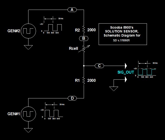
Scoobas Solution Sensing Tactic
This document serves multiple purposes, primarily to document the methods employed by a Scooba robot to detect: a) the presence of an acceptable cleaning solution being delivered to its pump, and b) the excess presence of used solution collected off...

Gate automatic lamp circuit
The circuit utilizes multiple integrated circuits to form an automatic lighting device that is activated by door and window sensors. It includes CD4093 digital integrated circuits, a relay, and a power supply circuit. The system typically remains closed when a...

Coop automatic controller circuit diagram
The automatic controller for a chicken coop is designed to automatically regulate light, temperature, and humidity, thereby enhancing egg production and survival rates of chickens. This device is intended for specialized poultry households in rural areas. The circuit operates through...

Automatic plant waterer
The unit consists of a sensor, timer, and electric water pump. The sensor is embedded in the soil, and when dry, the electronics operate the water pump for a preset time. The circuit is composed of a level-sensitive Schmitt trigger,...
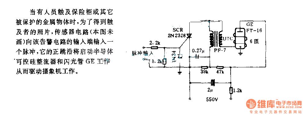
The alarm circuit diagram for safety box and other metal objects
When an individual touches the safety box or other protected metal objects, the sensor circuit generates a pulse to the alarm circuit. The positive edge of this pulse activates the semiconductor and thyristor flash GE, subsequently triggering the camera to...
The alarm circuit diagram for safety box and other metal objects
When an individual touches the safety box or other protected metal objects, the sensor circuit generates a pulse to the alarm circuit. The positive edge of this pulse activates the semiconductor and thyristor flash GE, subsequently triggering the camera to...

Electrical control circuit plow
The agriculture and electrical power harrow plow power cord must consist of four rubber cables, with one core wire designated as the ground wire. The traction machine housing must be properly grounded. The two traction power machines are connected to...