


Automatic bathroom light switch circuit CD4022 composed
#CD4022
#light switch
#automatic control
#sensor
#bathroom
#motion detection
#energy saving
#circuit design

Description: The circuit illustrated in the figure depicts an automatic bathroom light switch system. When the door is opened, the light is activated, illuminating the space. Conversely, when the door is opened again, the light turns off. The circuit comprises a hall switch, an octal counter, a pulse divider (CD4022), a Triac (VTH), and additional components.
The automatic bathroom light switch circuit operates based on the detection of the door's position through a hall effect sensor. This sensor detects magnetic fields and is typically positioned near the door frame, activating the circuit when a magnet, mounted on the door, comes into proximity.
Upon door entry, the hall switch is triggered, sending a signal to the octal counter (CD4022). This counter is designed to count the number of pulses it receives, which corresponds to the door's state (open or closed). The CD4022 is a binary counter that can count up to eight states, providing a reliable method for tracking the door's position.
The pulse divider function of the CD4022 is crucial as it ensures that each opening and closing of the door results in a single pulse being sent to the Triac. The Triac acts as a switch that controls the power to the bathroom light. When the Triac receives a signal from the counter, it allows current to flow to the light fixture, illuminating the bathroom.
For the circuit to function correctly, additional components such as resistors and capacitors may be included to stabilize the operation and prevent false triggering. The design ensures that the light remains on as long as the door is open and turns off automatically when the door is closed again. This automatic control not only enhances convenience but also contributes to energy savings by preventing unnecessary light usage.
Overall, this circuit design effectively combines several electronic components to create a user-friendly and energy-efficient lighting solution for bathroom environments. As shown in FIG bathroom light switch gated automatic way, when someone enters, once the door is opened, the light switch is turned on bright lights. When the out door is opene d once again, switch off the lights off. Circuit as shown in FIG. By the Hall switch circuit, octal counting, pulse divider CD4022 and Triac VTH and other components.
The automatic bathroom light switch circuit operates based on the detection of the door's position through a hall effect sensor. This sensor detects magnetic fields and is typically positioned near the door frame, activating the circuit when a magnet, mounted on the door, comes into proximity.
Upon door entry, the hall switch is triggered, sending a signal to the octal counter (CD4022). This counter is designed to count the number of pulses it receives, which corresponds to the door's state (open or closed). The CD4022 is a binary counter that can count up to eight states, providing a reliable method for tracking the door's position.
The pulse divider function of the CD4022 is crucial as it ensures that each opening and closing of the door results in a single pulse being sent to the Triac. The Triac acts as a switch that controls the power to the bathroom light. When the Triac receives a signal from the counter, it allows current to flow to the light fixture, illuminating the bathroom.
For the circuit to function correctly, additional components such as resistors and capacitors may be included to stabilize the operation and prevent false triggering. The design ensures that the light remains on as long as the door is open and turns off automatically when the door is closed again. This automatic control not only enhances convenience but also contributes to energy savings by preventing unnecessary light usage.
Overall, this circuit design effectively combines several electronic components to create a user-friendly and energy-efficient lighting solution for bathroom environments. As shown in FIG bathroom light switch gated automatic way, when someone enters, once the door is opened, the light switch is turned on bright lights. When the out door is opene d once again, switch off the lights off. Circuit as shown in FIG. By the Hall switch circuit, octal counting, pulse divider CD4022 and Triac VTH and other components.

case stepper
Beige Bag Software has been offering affordable and innovative circuit design tools since 1990. B2 Spice provides schematics as well as analog, digital, and mixed-mode electronic circuit simulation. It integrates with EAGLE and CADSTAR PCB software.
B2 Spice is a powerful...

Wire Break Sensor Alarm Circuit Schematic
The circuit of a loop sensor-based simple security alarm is described here. The sensor loop consists of a short length of thin enamelled copper wire.
The loop sensor security alarm operates on the principle of detecting interruptions in the circuit formed...

Light Switch
Light Switch. This is a light switch or light-activated relay circuit. The relay activates when the light-dependent resistor (LDR) is uncovered and deactivates when the LDR is covered. It is adjustable for sensitivity and includes an LED indicator.
This light-activated relay...

Motion Activated Camera
A straightforward attachment for a Canon SLR camera designed to create a motion-activated camera using an Arduino. This project draws inspiration from the intervalometer project at The Honey Jar, with modifications made to the circuit by utilizing a 4N35 optocoupler...

eliminate wasted phantom power
Most Apple and Windows PCs can enter "sleep" or "standby" mode when not in use instead of being completely shut down. This mode allows the operating system to restore all previous work sessions within seconds upon waking via keyboard or...

Automatic light regulator circuit diagram
This circuit is designed to automatically adjust the brightness of lights based on the ambient light intensity. In bright conditions, the lights remain off, while in low ambient brightness, the lights are activated. The circuit incorporates a thyristor (VT1) and...

The electronic energy saving lamp maintenance circuit diagram
The saving lamp circuit features two main types: glass cover and exposed. The glass cover variants include three series: spherical, cylindrical, and processing types. The first two series consist of four variations: transparent, carved, engraved, and white. These lamps are...

Automatic plant waterer
The unit consists of a sensor, timer, and electric water pump. The sensor is embedded in the soil, and when dry, the electronics operate the water pump for a preset time. The circuit is composed of a level-sensitive Schmitt trigger,...
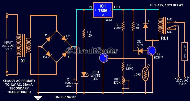
Automatic Light Controller Using 7806 And LDR PCB
This circuit automates the control of street or porch lights. The automatic lamp controller circuit utilizes a 7806 voltage regulator IC, which can be employed to automate street lights, tube lights, or any other home electrical lighting systems. The IC...