


controlling CFLs with SSRs

Description: A request has been made to automate certain functions within a residence, specifically to control the on and off states of CFL lamps using a triac that is coupled to a logic circuit via a zero-crossing detection mechanism.
To achieve the automation of CFL lamp control using a triac, a circuit can be designed that incorporates a zero-crossing detector, a microcontroller or logic circuit, and the triac itself. The zero-crossing detector is essential for ensuring that the triac is triggered at the optimal moment, which minimizes electrical noise and reduces the stress on the lamp and circuit components.
The circuit will typically include an opto-isolator that serves as an interface between the high-voltage AC line and the low-voltage control logic. The opto-isolator provides electrical isolation, protecting the microcontroller from high voltage spikes. The zero-crossing detection circuit can be implemented using a comparator or dedicated zero-crossing detection IC, which monitors the AC waveform and outputs a signal when the voltage crosses zero.
The microcontroller receives the zero-crossing signal and determines the appropriate timing for triggering the triac. By controlling the phase angle at which the triac is turned on, the brightness of the CFL lamp can be adjusted, allowing for dimming capabilities in addition to simple on/off control.
The triac itself is connected in series with the lamp, and when triggered by the microcontroller, it allows current to flow through the lamp, turning it on. When the microcontroller ceases to trigger the triac, it will turn off the lamp at the next zero crossing of the AC waveform.
Additional components such as resistors, capacitors, and possibly a snubber circuit may be required to protect the triac from voltage spikes and to ensure stable operation. Overall, this circuit design provides a robust and efficient method for automating the control of CFL lamps in a residential setting.Hello, I`d like to automate some functions in my house, particularly, turn on and off CFL lamps with a triac coupled to the logic via a zero crossing..
To achieve the automation of CFL lamp control using a triac, a circuit can be designed that incorporates a zero-crossing detector, a microcontroller or logic circuit, and the triac itself. The zero-crossing detector is essential for ensuring that the triac is triggered at the optimal moment, which minimizes electrical noise and reduces the stress on the lamp and circuit components.
The circuit will typically include an opto-isolator that serves as an interface between the high-voltage AC line and the low-voltage control logic. The opto-isolator provides electrical isolation, protecting the microcontroller from high voltage spikes. The zero-crossing detection circuit can be implemented using a comparator or dedicated zero-crossing detection IC, which monitors the AC waveform and outputs a signal when the voltage crosses zero.
The microcontroller receives the zero-crossing signal and determines the appropriate timing for triggering the triac. By controlling the phase angle at which the triac is turned on, the brightness of the CFL lamp can be adjusted, allowing for dimming capabilities in addition to simple on/off control.
The triac itself is connected in series with the lamp, and when triggered by the microcontroller, it allows current to flow through the lamp, turning it on. When the microcontroller ceases to trigger the triac, it will turn off the lamp at the next zero crossing of the AC waveform.
Additional components such as resistors, capacitors, and possibly a snubber circuit may be required to protect the triac from voltage spikes and to ensure stable operation. Overall, this circuit design provides a robust and efficient method for automating the control of CFL lamps in a residential setting.Hello, I`d like to automate some functions in my house, particularly, turn on and off CFL lamps with a triac coupled to the logic via a zero crossing..

solid state relay
A Solid State Relay is not a traditional relay; it consists solely of an electronic circuit that performs the switching function. It operates similarly to a relay, allowing a low voltage to control a higher voltage, offering advantages over conventional...

Triac low output problem
The circuit consists of two separate 3023 optoisolators controlling two distinct triacs, each responsible for powering a large 3-phase contactor. One contactor operates correctly, while the other experiences issues, not receiving sufficient power to engage fully. The upper image illustrates...

Triac lamp dimmer
A heatsink allows the TRIAC (TR1) to manage a maximum power of 350 watts. The neon lamp, II, will not activate the gate until the TRIAC begins conducting, and resistor R1 can be adjusted to set the desired lighting level.
The...

High-Power Long-Life Compact Fluorescent Lamp / Tube lamp Controller
The UBA2021 can be utilized as a 600 V lamp controller and half-bridge driver integrated circuit (IC) for high-power applications. It is designed for long-life compact fluorescent lamp (CFL) and tubular fluorescent lamp (TL) applications.
The UBA2021 is a versatile integrated...

switching ac loads triac
A circuit is needed to control a couple of large AC solenoid valves and several single-phase AC motors. The line voltage is 132VAC, with the solenoids drawing 1A and the motors drawing 13A and 27A when operating. The goal is...
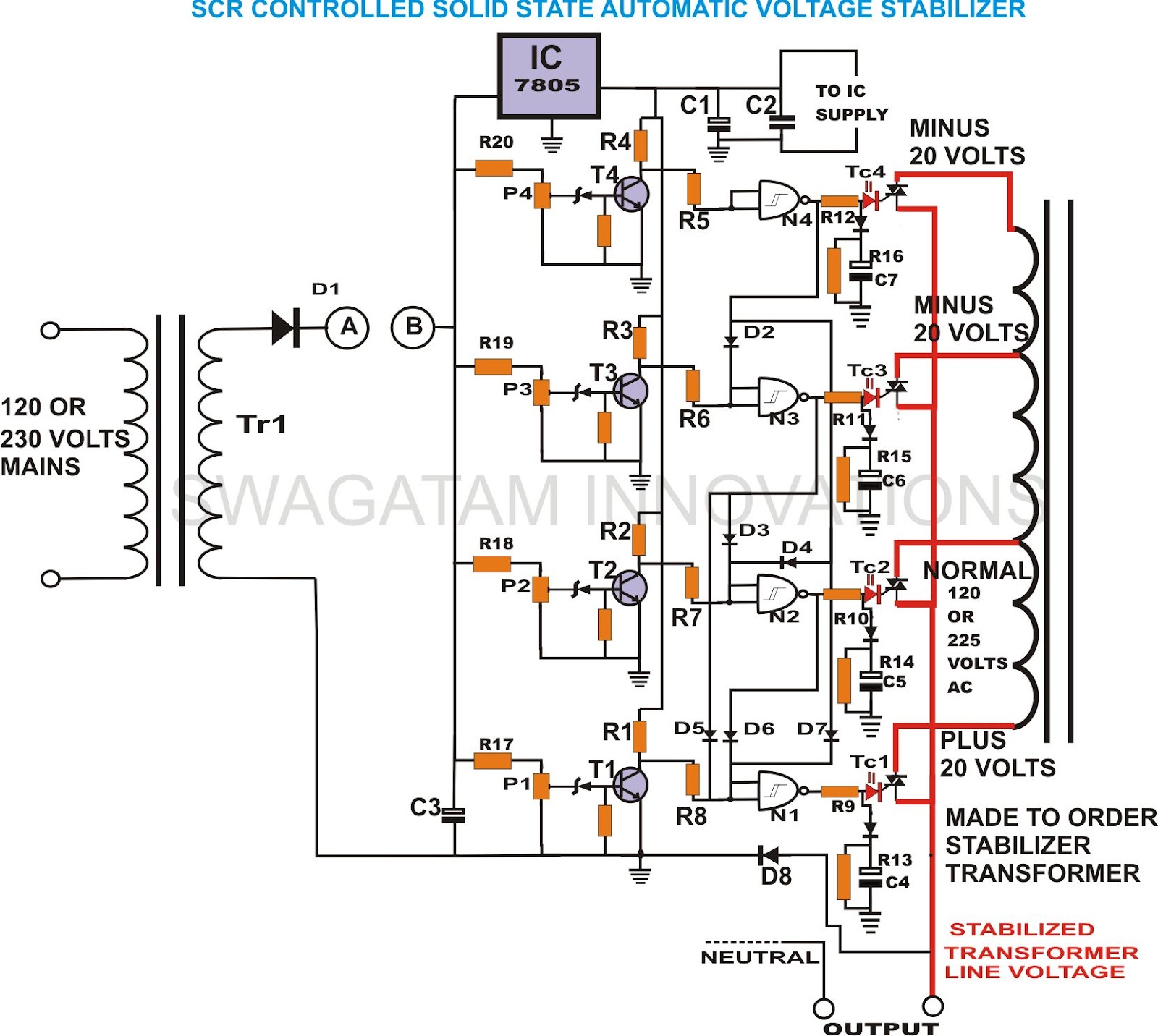
build solid state scrtriac controlled
This unique and hard-to-find triac-controlled AC voltage stabilizer circuit has been specifically designed for efficient voltage stabilization. With a solid-state design, the voltage switching transitions are smooth, resulting in minimal wear and tear. The proposed circuit provides four-step voltage stabilization...

ac Validate Triac circuit
The heatsink on the triac is somewhat unclear. A maximum value of 10°C/W has been calculated, which raises concerns. The calculation is as follows: (maximum temperature - room temperature) / (maximum on-stage voltage * (milliamps / voltage) - junction-to-base thermal...

Triac regulation of mains voltage
Triac regulation is designed to control the power of mains appliances. It can adjust the brightness of incandescent light bulbs, halogen lamps, dimmable energy savers, heaters, and other thermal devices, as well as regulate motors. The power can be easily...

Triac zero voltage switching
The triac will be activated at the beginning of the positive half cycle due to the current flowing through the 3 µF capacitor, provided that the C103 SCR is in the off state. The load voltage subsequently charges the 1...