


3V to 9V DC Converters
#DC converter
#TL496
#power supply
#voltage boost
#battery replacement
#electrolytic capacitor
#coil
#3V to 9V
#simple circuit
#energy efficient

Description: This document presents several DC converter circuits that convert input voltages from 3V to 9V. These converters can be particularly useful in scenarios where a 9V battery is not available or deemed too costly. The first circuit is straightforward, utilizing the TL496 power supply controller, an inductor, and an electrolytic capacitor. The maximum output current is 405mA, with a no-load current consumption of 125µA, resulting in an estimated battery life of approximately 166 days.
The described circuit operates as a step-up (boost) converter, which is essential for applications requiring a higher voltage output than the input voltage. The TL496 is a versatile integrated circuit designed for power supply regulation, and its inclusion in this circuit allows for efficient voltage conversion.
The circuit architecture typically consists of the TL496 configured in a feedback loop to regulate the output voltage. The inductor stores energy when the switch (often a transistor controlled by the TL496) is closed and releases it to the output when the switch is opened. The electrolytic capacitor smooths the output voltage, ensuring a stable DC output suitable for powering devices that require a 9V supply.
The input current specification indicates that at maximum output, the circuit draws 405mA from the input source, which is a critical parameter for battery-powered applications. The no-load current consumption of 125µA signifies the efficiency of the circuit when idle, allowing for prolonged battery life, estimated at around 166 days under optimal conditions.
Such converters are invaluable in portable electronic devices, where battery life and cost-effectiveness are significant concerns. The simplicity of the design also makes it accessible for hobbyists and engineers looking to implement efficient power solutions in their projects.Here are some 3V to 9V DC converter circuits that were requested by some of our visitors. It may be helpful to have one of this converters when no 9V battery is available or if you consider that they are too expensive. The first circuit is very simple, it uses the TL496 power supply controller, a coil and a electrolytic capacitor.
The input curren t (the current drawn from the batteries) is 405mA at the maximum output current. Without load the current consumption is 125 µA and the batteries life is around 166 days.
The described circuit operates as a step-up (boost) converter, which is essential for applications requiring a higher voltage output than the input voltage. The TL496 is a versatile integrated circuit designed for power supply regulation, and its inclusion in this circuit allows for efficient voltage conversion.
The circuit architecture typically consists of the TL496 configured in a feedback loop to regulate the output voltage. The inductor stores energy when the switch (often a transistor controlled by the TL496) is closed and releases it to the output when the switch is opened. The electrolytic capacitor smooths the output voltage, ensuring a stable DC output suitable for powering devices that require a 9V supply.
The input current specification indicates that at maximum output, the circuit draws 405mA from the input source, which is a critical parameter for battery-powered applications. The no-load current consumption of 125µA signifies the efficiency of the circuit when idle, allowing for prolonged battery life, estimated at around 166 days under optimal conditions.
Such converters are invaluable in portable electronic devices, where battery life and cost-effectiveness are significant concerns. The simplicity of the design also makes it accessible for hobbyists and engineers looking to implement efficient power solutions in their projects.Here are some 3V to 9V DC converter circuits that were requested by some of our visitors. It may be helpful to have one of this converters when no 9V battery is available or if you consider that they are too expensive. The first circuit is very simple, it uses the TL496 power supply controller, a coil and a electrolytic capacitor.
The input curren t (the current drawn from the batteries) is 405mA at the maximum output current. Without load the current consumption is 125 µA and the batteries life is around 166 days.

Battery charger or Power Supply 14 volt 4 ampere
The schematic diagram originates from a circuit designed as a battery charger/power supply with an output of 14V and a maximum current of 4A, utilizing the VN64GA MOSFET. This high-performance battery charger is specifically engineered for gelled electrolyte lead-acid batteries,...

250 Watt PC power Supply
Up to 10 A continuous output current, or operation with 50 % ESD and 18 A peak current are possible without a fan if sufficient natural air flow is present and the ambient temperature does not exceed 30 °C. A...

MDRC Mark 4 20 Amp Power Supply
The MDRC committee approached the author to take on the role of Electronic Components and Project Officer, which was accepted without hesitation. Upon assuming the position, it became evident that more time would be required than initially anticipated, primarily for...

Batteries charger & PSU - ideal for digital camerass
This circuit was designed for digital cameras, which are known to have significant power consumption. For instance, the Minolta E223 camera requires approximately 800 mA. In practice, this demand can be met using a mains power supply or high-capacity NiMH...

FSP107-2PS01 two-in-one power panel circuit analysis
The main component is the LG26 one-inch screens integrated with the FSP107-2PS01 two-in-one electrical power package, which utilizes a direct drive CCFL modulator tube. This setup is compatible with screens from other manufacturers, such as Samsung and AU, but requires...

Auto Fuse for power supply
The power supply, with electronic stabilization - mainly those of laboratories - should be protected from overcurrent that emanates from short-circuits, erroneous association, or damage of repaired appliances. The circuit offers effective protection in power supply with output voltage up...
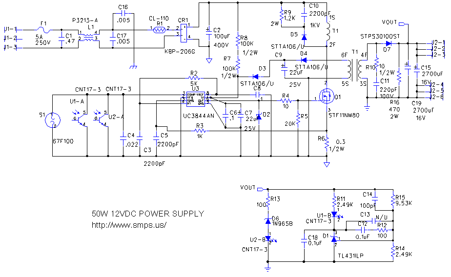
switching power supply 2
This circuit is designed to double nearly any DC input voltage while handling a substantial amount of current. For instance, it can work with input voltages ranging from 12 to 24V. With minor modifications, it can also provide any desired...

Output sampling winding isolated switching power supply
The diagram illustrates the output sampling winding of an isolated switching power supply. In the diagram, T represents a high-frequency transformer; N2 denotes the self-oscillation positive feedback winding; N3 is the error amplifier; VTS is the winding that provides the...

Battery Replacement Power Supply
The battery-operated toy has malfunctioned, necessitating repair. Upon disassembly, the battery compartment may be disconnected from the circuitry, or the batteries might be depleted. A solution is to implement a switchable power supply designed to replace one to six dry...