


ADP2323 high current DC DC converter circuit design electronic project
#DC DC converter
#ADP2323
#high current
#voltage regulation
#power supply
#dual output
#electronic circuit
#1V output
#5V output
#2A output

Description: The ADP2323 DC-DC converter is designed to deliver two output voltages with specified maximum output currents. The first channel provides a 5-volt output with a maximum current of 2 Amperes, while the second channel supplies 1 volt with a maximum load current of 1 Ampere.
The ADP2323 is a highly efficient step-down (buck) DC-DC converter that integrates a switching controller and power MOSFETs to achieve high performance in a compact design. The device operates with an input voltage range typically from 4.5V to 18V, making it suitable for various applications, including portable devices, industrial equipment, and automotive systems.
The first output channel, configured to provide 5V at 2A, can be utilized for powering microcontrollers, sensors, and other peripherals that require stable voltage levels with higher current demands. The output voltage is regulated through a feedback loop that adjusts the duty cycle of the internal switching mechanism, ensuring minimal voltage ripple and efficient power conversion.
The second output channel, which provides 1V at 1A, can be particularly beneficial for low-voltage digital circuits or for powering specific components that operate at lower voltage levels. This channel also employs a feedback mechanism to maintain the output voltage within specified limits under varying load conditions.
The ADP2323 features built-in protection mechanisms, including overcurrent protection and thermal shutdown, ensuring reliable operation under fault conditions. Additionally, it can be configured with external components to optimize performance parameters such as switching frequency, output capacitance, and inductor selection, further enhancing its versatility in different circuit designs.
Overall, the ADP2323 DC-DC converter is a robust solution for applications requiring dual voltage outputs with varying current capacities, combining efficiency, reliability, and compactness in its design.This ADP2323 DC DC converter will provide two output voltages at two maximum output current. On the first channel this electronic circuit will provide a 5 volt output voltage at a maximum output current of 2 Ampere and at the second output channel this circuit will provide a 1 volt at a maximum load current of 1 Ampere.
The ADP2323 is a highly efficient step-down (buck) DC-DC converter that integrates a switching controller and power MOSFETs to achieve high performance in a compact design. The device operates with an input voltage range typically from 4.5V to 18V, making it suitable for various applications, including portable devices, industrial equipment, and automotive systems.
The first output channel, configured to provide 5V at 2A, can be utilized for powering microcontrollers, sensors, and other peripherals that require stable voltage levels with higher current demands. The output voltage is regulated through a feedback loop that adjusts the duty cycle of the internal switching mechanism, ensuring minimal voltage ripple and efficient power conversion.
The second output channel, which provides 1V at 1A, can be particularly beneficial for low-voltage digital circuits or for powering specific components that operate at lower voltage levels. This channel also employs a feedback mechanism to maintain the output voltage within specified limits under varying load conditions.
The ADP2323 features built-in protection mechanisms, including overcurrent protection and thermal shutdown, ensuring reliable operation under fault conditions. Additionally, it can be configured with external components to optimize performance parameters such as switching frequency, output capacitance, and inductor selection, further enhancing its versatility in different circuit designs.
Overall, the ADP2323 DC-DC converter is a robust solution for applications requiring dual voltage outputs with varying current capacities, combining efficiency, reliability, and compactness in its design.This ADP2323 DC DC converter will provide two output voltages at two maximum output current. On the first channel this electronic circuit will provide a 5 volt output voltage at a maximum output current of 2 Ampere and at the second output channel this circuit will provide a 1 volt at a maximum load current of 1 Ampere.

Batteries charger & PSU - ideal for digital camerass
This circuit was designed for digital cameras, which are known to have significant power consumption. For instance, the Minolta E223 camera requires approximately 800 mA. In practice, this demand can be met using a mains power supply or high-capacity NiMH...

Variable Voltage Regulation
Controlling the output voltage from a regulator can be made variable in three ways:
1. Using a fixed reference zener diode to increase the output by the value of the zener
2. A variable resistor for variable output, note that...

Power Supply Failure Alarm
This is a specialized circuit design for a power supply failure alarm. Most power supply failure alarm or indicator circuits require an independent power supply. However, the alarm circuit presented here...
The power supply failure alarm circuit is designed to monitor...

Structural analysis of switching power supply
A daily switching power supply primarily provides direct current (DC) power to electronic devices. The required DC voltage for electronic devices typically ranges from several volts to over ten volts, while the input voltage from the mains supply is either...
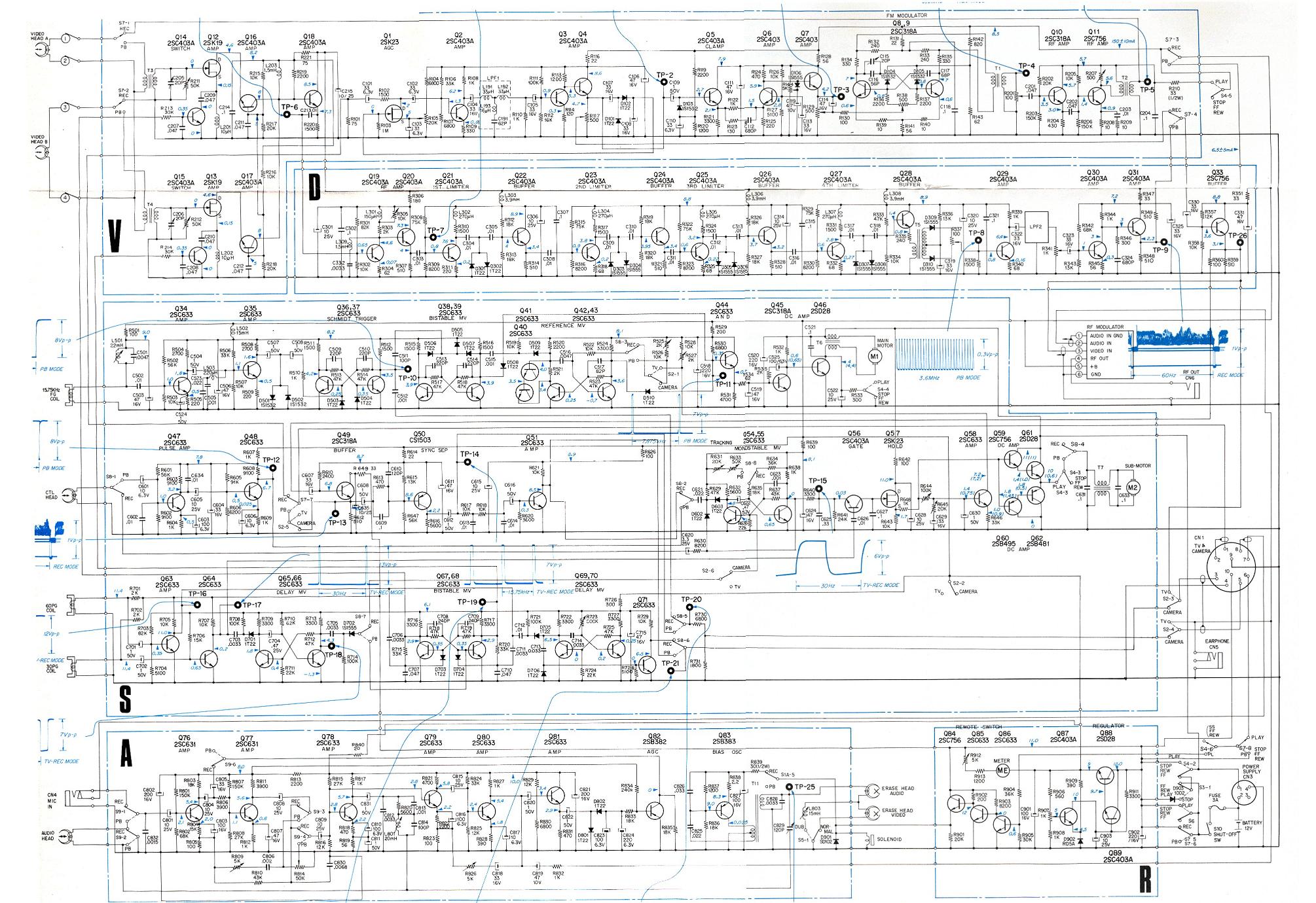
Eng Sony AV 3400
The original power supply AC-3400 features a charger function. In addition to the power button and the indicator light for power status, the front panel includes a charge level indicator for the accumulator, a start button, and a socket for...
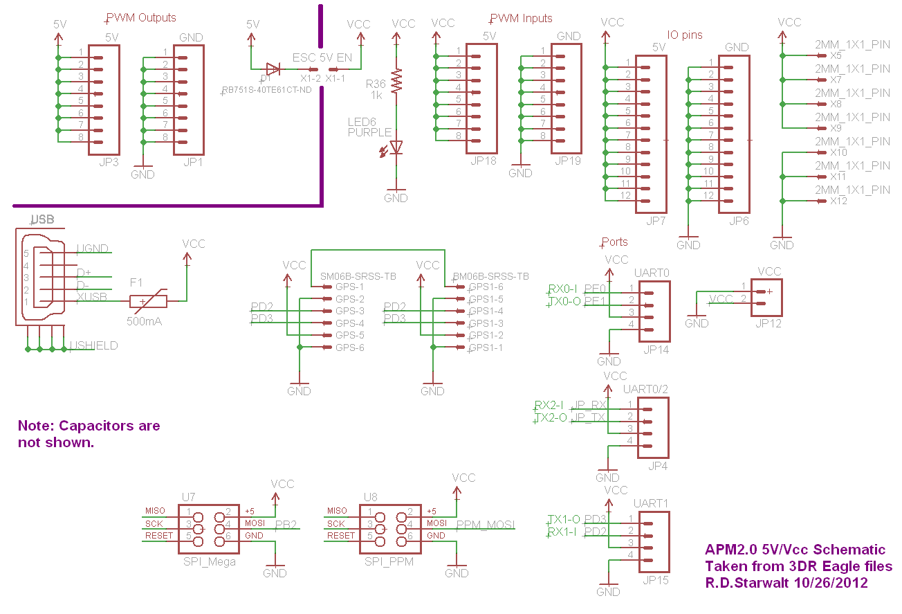
APM2.0 5V/Vcc Schematic
The PWM Output section has been separated into the upper left corner, delineated by a heavy purple line that is bridged by jumper JP1 on the APM2.0. This design choice highlights that diode D1 allows current to pass through JP1,...

car battery charger schematics
The circuit is designed to be powered directly by a power supply, which is why it does not include a transformer, rectifier, or filter capacitors in the schematic. However, the addition of these components is possible. To operate the circuit,...

35W switching power supply circuit having a set-top box output of 5
A 35W switching power supply circuit designed for a set-top box output is depicted in Figure 5. It features five distinct voltage outputs: Uo1 (+30V, 100mA), Uo2 (+18V, 550mA), Uo3 (+5V, 2.5A), Uo4 (+3.3V, 3A), and Uo5 (-5V, 100mA). The...
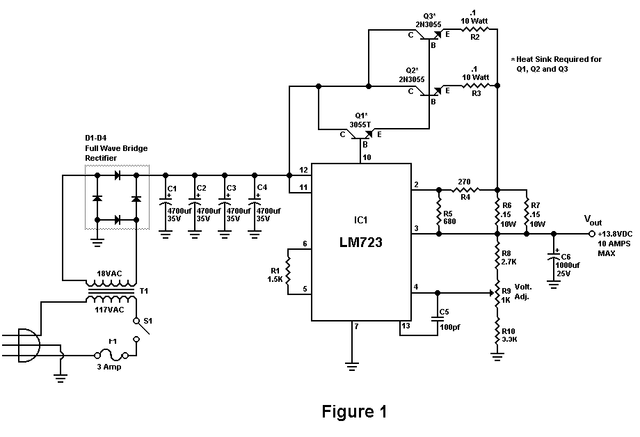
Build A 10 Amp 13.8 Volt Power Supply
Sometimes amateurs like to home-brew their power supplies instead of purchasing one off the shelf at any of the major ham radio retail dealers. The advantage to rolling your own power supply is that it teaches us how they work...