


Coin cell battery to 3.3V with Joule Thief circuit
#joule thief
#voltage booster
#coin cell
#3.3V
#energy harvesting
#low power
#oscillator
#DIY electronics
#battery life extender
#simple circuit
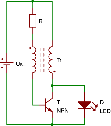
Description: It is a self-oscillating voltage booster. It is relatively simple to build and it will allow you to use almost all the power in the battery, even when its voltage is low.
The self-oscillating voltage booster is a circuit designed to increase voltage from a lower level to a higher level, making it particularly useful in applications where battery power is limited. This type of circuit operates without the need for an external clock signal, relying instead on the feedback mechanism inherent in its design to generate oscillations.
Typically, the circuit consists of an inductor, a switch (often a transistor), a diode, and a capacitor. The operation begins when the switch is closed, allowing current to flow through the inductor, which stores energy in the form of a magnetic field. When the switch opens, the sudden collapse of the magnetic field generates a high voltage across the inductor. This high voltage is directed through the diode to the output capacitor, where it is stored for use.
The simplicity of this design lies in its ability to self-oscillate. The feedback loop created by the inductor and the switch ensures that the circuit continues to operate without external control. As the output voltage rises, the circuit can adapt to varying load conditions, maintaining stable output even as the input voltage from the battery decreases.
This voltage booster is particularly effective in applications such as powering LEDs, microcontrollers, and other low-power devices where battery efficiency is crucial. By maximizing the usable energy from the battery, this circuit can extend the operational life of battery-powered devices, making it an invaluable component in portable electronics.
Proper selection of components, particularly the inductor and switching transistor, is essential for optimizing performance. The inductor must be chosen based on the desired output voltage and current, while the transistor should be capable of handling the switching frequency and power levels involved. Additionally, the output capacitor should be selected to minimize voltage ripple, ensuring a stable supply to the load.
Overall, the self-oscillating voltage booster represents an efficient and effective solution for voltage conversion in battery-operated devices, facilitating maximum utilization of available energy.It is a self-oscillating voltage booster. It is relatively simple to build and it will allow you to use almost all the power in the battery, even when its
The self-oscillating voltage booster is a circuit designed to increase voltage from a lower level to a higher level, making it particularly useful in applications where battery power is limited. This type of circuit operates without the need for an external clock signal, relying instead on the feedback mechanism inherent in its design to generate oscillations.
Typically, the circuit consists of an inductor, a switch (often a transistor), a diode, and a capacitor. The operation begins when the switch is closed, allowing current to flow through the inductor, which stores energy in the form of a magnetic field. When the switch opens, the sudden collapse of the magnetic field generates a high voltage across the inductor. This high voltage is directed through the diode to the output capacitor, where it is stored for use.
The simplicity of this design lies in its ability to self-oscillate. The feedback loop created by the inductor and the switch ensures that the circuit continues to operate without external control. As the output voltage rises, the circuit can adapt to varying load conditions, maintaining stable output even as the input voltage from the battery decreases.
This voltage booster is particularly effective in applications such as powering LEDs, microcontrollers, and other low-power devices where battery efficiency is crucial. By maximizing the usable energy from the battery, this circuit can extend the operational life of battery-powered devices, making it an invaluable component in portable electronics.
Proper selection of components, particularly the inductor and switching transistor, is essential for optimizing performance. The inductor must be chosen based on the desired output voltage and current, while the transistor should be capable of handling the switching frequency and power levels involved. Additionally, the output capacitor should be selected to minimize voltage ripple, ensuring a stable supply to the load.
Overall, the self-oscillating voltage booster represents an efficient and effective solution for voltage conversion in battery-operated devices, facilitating maximum utilization of available energy.It is a self-oscillating voltage booster. It is relatively simple to build and it will allow you to use almost all the power in the battery, even when its

Wide-range-oscillator
The gain control enables the oscillator to maintain a nearly constant output across its range. The circuit operates within a frequency range of 160 kHz to 12 MHz while producing a consistent amplitude.
The oscillator circuit described utilizes a gain control...

Oscillator-clock-generator
This self-starting fixed-frequency oscillator circuit provides excellent frequency stability. R1 and C1 form the frequency-determining network, while R2 delivers the regenerative feedback. Diode D1 improves stability by compensating for the difference between VaH and VsurrLY. In applications where a precision...

Joule Thief
The circuit consists of four main components: an indicator LED, a hand-wound coil, a 1k resistor, and a 2N4401 transistor. The coil is made from solid core telephone wire, with a total of 14 turns wound around the core, creating...

Joule Thief circuit as a battery charger
Excellent Joule thief circuit idea!
The Joule Thief is a simple yet effective circuit designed to extract usable voltage from low-voltage power sources, such as depleted batteries. This circuit operates on the principle of boosting voltage through the use of...

Very Low Distortion Oscillator
This oscillator utilizes a bridge circuit with an optoisolator functioning as a gain-control device. The resultant distortion can be maintained at 9 ppm (0.0009%) with appropriate adjustments.
The oscillator circuit described operates using a bridge configuration, which is a common approach...

Joulethief SEC exciter and variants 68
Design an efficient receiver/collector that can withstand a beam impact, potentially utilizing a large photomultiplier array. The system should employ a beam mode and wavelength that is not easily attenuated. In this scenario, explosive bursts from option 1 may be...
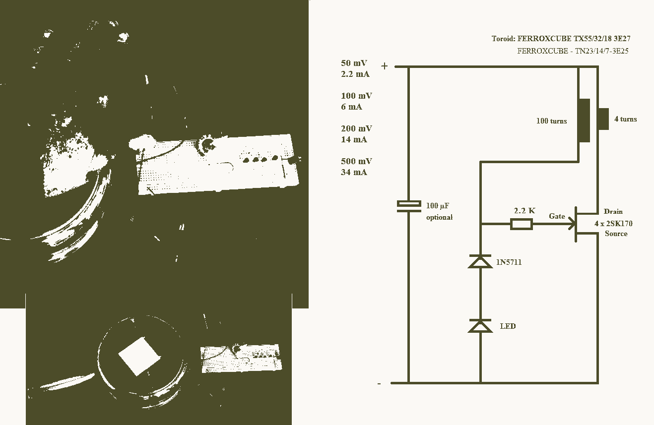
25mV Joule Thief circuit
A 25mV Joule Thief powered by a Peltier device that utilizes body heat.
The 25mV Joule Thief circuit is an innovative energy harvesting solution that converts the minimal voltage generated by a Peltier device into usable electrical energy. The Joule Thief...

Inductance feedback oscillator circuit
A feedback oscillator circuit utilizing inductance is presented, featuring the 3DG3 transistor. The component parameters reference values include: 1) transistors 3DG6, 2) resistances R1 at 91 kΩ, R2 at 11 kΩ, and R3 unspecified, 3) capacitance values of C at...
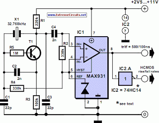
Very Low Power 32kHz Oscillator
The 32-kHz low-power clock oscillator provides several advantages compared to traditional oscillator circuits that utilize a CMOS inverter. These inverter circuits often exhibit issues such as significant fluctuations in supply currents across a 3V to 6V supply range, making it...