


DC-to-DC AC inverter
#DC-to-AC
#inverter
#power amplifier
#astable multivibrator
#transformer
#frequency
#low cost
#1200 Hz
#power supply
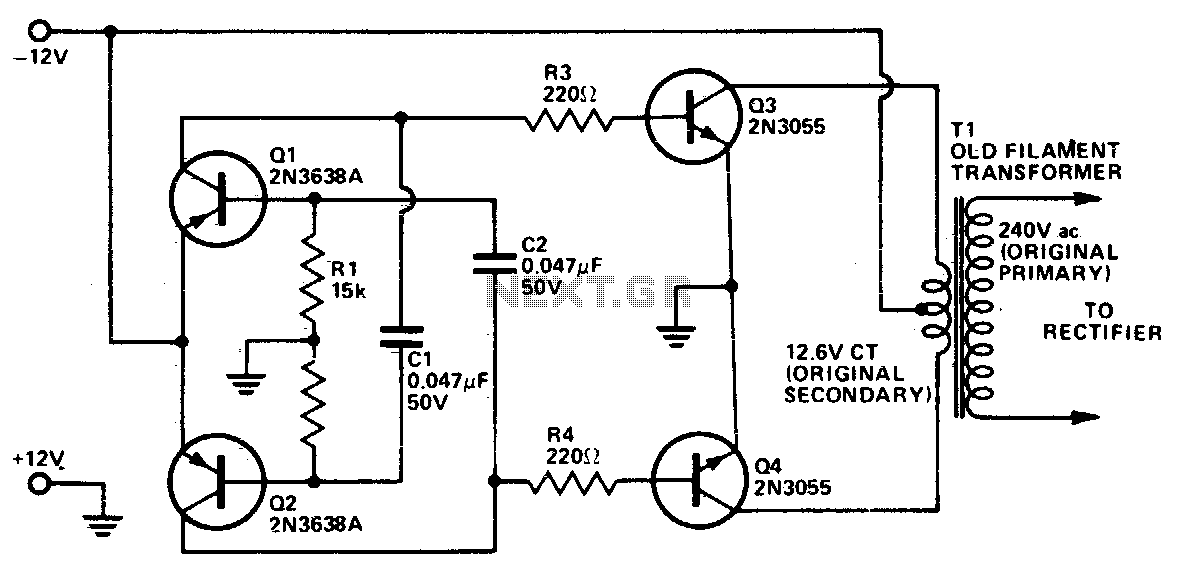
Description: This inverter utilizes standard components instead of specialized parts like the toroidal transformer commonly found in many inverters. The design maintains a low cost by employing inexpensive, readily available components. Essentially, it functions as a power amplifier driven by an astable multivibrator. The operating frequency is approximately 1200 Hz, which is manageable for most 50/60 Hz power transformers, minimizing losses. If any issues arise, increasing the values of capacitors C1 and C2 will reduce the frequency. Additionally, the rectifier filtering capacitors needed are significantly smaller due to the higher operating frequency. The two 2N3055 transistors should be mounted on a suitably sized heatsink. The transformer must be rated according to the required output power, accounting for a conversion efficiency of around 60%.
This inverter circuit operates as a cost-effective solution for converting DC power to AC power. The core of the design is an astable multivibrator, which generates a square wave signal at approximately 1200 Hz. This frequency is particularly advantageous, as it allows standard 50/60 Hz transformers to operate efficiently, thereby reducing energy loss during the conversion process.
The inverter employs two 2N3055 transistors, which are standard NPN power transistors capable of handling high currents. These transistors are configured in a push-pull arrangement, which effectively amplifies the square wave signal produced by the multivibrator. It is crucial for the transistors to be mounted on a heatsink to dissipate the heat generated during operation, preventing thermal overload and ensuring reliability.
In terms of components, capacitors C1 and C2 play a significant role in determining the oscillation frequency of the multivibrator. If the output frequency needs adjustment due to performance issues or load requirements, increasing the capacitance of these capacitors will lower the frequency, allowing for better compatibility with specific transformer designs.
The inverter's transformer must be selected based on the desired output power. It is essential to consider the conversion efficiency, which is estimated at around 60%. This means that the transformer should be rated higher than the expected output to accommodate losses and ensure stable operation. The rectifier filtering capacitors, which smooth the output waveform, are smaller in value due to the higher frequency of operation, thus enhancing the overall compactness and efficiency of the circuit.
Overall, this inverter design exemplifies a practical approach to power conversion, leveraging readily available components while maintaining a focus on cost-effectiveness and operational efficiency.This inverter uses no special components such as the torodial transformer used in many inverters. Cost is kept low with the use of cheap, readily available components. Essentially, it is a power amplifier driven by an asta-ble multivibrator. The frequency is around 1200 Hz which most 50/60 Hz power transformers handle well without too much loss. Increasing the value of capacitors Cl and C2 will lower the frequency if any trouble is experienced However, rectifier filtering capacitors required are considerably smaller at the higher operating frequency. The two 2N3055 transistor should be mounted on an adequately sized heatsink. The transformer should be rated ac-cordingto the amount of output power required allowing for conversion efficiency of approximately 60%.
This inverter circuit operates as a cost-effective solution for converting DC power to AC power. The core of the design is an astable multivibrator, which generates a square wave signal at approximately 1200 Hz. This frequency is particularly advantageous, as it allows standard 50/60 Hz transformers to operate efficiently, thereby reducing energy loss during the conversion process.
The inverter employs two 2N3055 transistors, which are standard NPN power transistors capable of handling high currents. These transistors are configured in a push-pull arrangement, which effectively amplifies the square wave signal produced by the multivibrator. It is crucial for the transistors to be mounted on a heatsink to dissipate the heat generated during operation, preventing thermal overload and ensuring reliability.
In terms of components, capacitors C1 and C2 play a significant role in determining the oscillation frequency of the multivibrator. If the output frequency needs adjustment due to performance issues or load requirements, increasing the capacitance of these capacitors will lower the frequency, allowing for better compatibility with specific transformer designs.
The inverter's transformer must be selected based on the desired output power. It is essential to consider the conversion efficiency, which is estimated at around 60%. This means that the transformer should be rated higher than the expected output to accommodate losses and ensure stable operation. The rectifier filtering capacitors, which smooth the output waveform, are smaller in value due to the higher frequency of operation, thus enhancing the overall compactness and efficiency of the circuit.
Overall, this inverter design exemplifies a practical approach to power conversion, leveraging readily available components while maintaining a focus on cost-effectiveness and operational efficiency.This inverter uses no special components such as the torodial transformer used in many inverters. Cost is kept low with the use of cheap, readily available components. Essentially, it is a power amplifier driven by an asta-ble multivibrator. The frequency is around 1200 Hz which most 50/60 Hz power transformers handle well without too much loss. Increasing the value of capacitors Cl and C2 will lower the frequency if any trouble is experienced However, rectifier filtering capacitors required are considerably smaller at the higher operating frequency. The two 2N3055 transistor should be mounted on an adequately sized heatsink. The transformer should be rated ac-cordingto the amount of output power required allowing for conversion efficiency of approximately 60%.
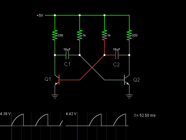
Astable Multivibrator (Oscillator)
This circuit functions as an astable multivibrator, also known as an oscillator. The two transistors are interconnected in a manner that allows the circuit to alternate between two states. In one state, the base of transistor Q1 is approximately one...

Output sampling winding isolated switching power supply
The diagram illustrates the output sampling winding of an isolated switching power supply. In the diagram, T represents a high-frequency transformer; N2 denotes the self-oscillation positive feedback winding; N3 is the error amplifier; VTS is the winding that provides the...

FSP107-2PS01 two-in-one power panel circuit analysis
The main component is the LG26 one-inch screens integrated with the FSP107-2PS01 two-in-one electrical power package, which utilizes a direct drive CCFL modulator tube. This setup is compatible with screens from other manufacturers, such as Samsung and AU, but requires...

testing troubleshooting inverter
Connect 22k fixed resistors across each transistor base and ground, then connect the leads of a 50K dual potentiometer across these resistors to imitate variations similar to a 10k potentiometer. Remove the 10K resistors connected to the base of each...

Power Amplifier Speaker Protection Circuit Schematic
Power Amplifier Speaker Protection Circuit Schematic. When a power amplifier is switched on, a loud thump sound is often heard due to a sudden heavy discharge.
The power amplifier speaker protection circuit is designed to prevent loud thump sounds during the...

12V Inverter Circuit Using 4013
This circuit diagram for a 12V inverter is simple to construct and utilizes inexpensive components that many electronics hobbyists may already possess. While it is feasible to create a more powerful circuit, the complexity arises from managing the significant currents...

Sanyo 83P switching power supply circuit diagram
Oscillation: The positive terminal voltage of C310 is approximately 300V. The resistors R311 and R312 are connected to the switch BG311 at the B pole, while the B301 winding via the switching transformer (4) and (6) is connected to the...
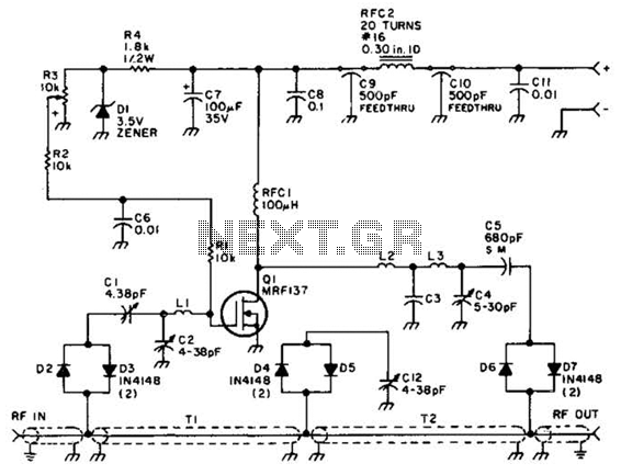
2M Fet Power Amplifier Circuit
Using a power MOSFET, this amplifier can achieve a 2-W handheld radio power level, increasing it to approximately 10 W on the 2-meter band. A transmission-line RF switch is employed for transmit/receive (T/R) switching.
The described amplifier utilizes a power MOSFET...
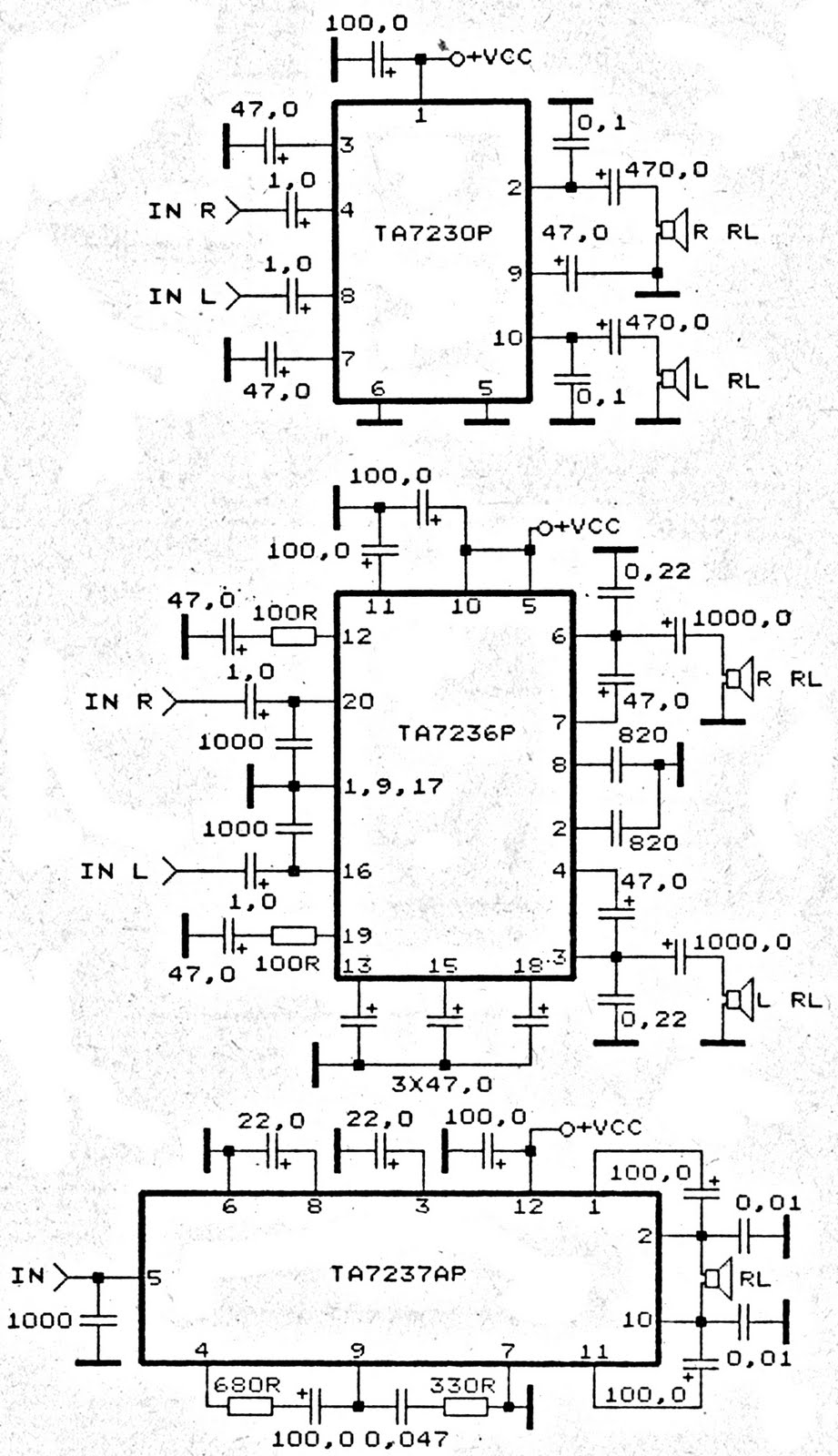
ta7230p ta7236p ta7237ap amplifier
The amplifier circuit is based on integrated circuits (ICs) that determine the gain. Three specific ICs, TA7230P, TA7236P, and TA7237AP, are utilized as power amplifiers. Each IC has distinct output characteristics and input voltage requirements. All three ICs are manufactured...