


MAX641 high current step-up converter
#MAX641
#step-up converter
#high current
#voltage converter
#low battery detector
#Maxim IC
#DC-DC converter
#power electronics
#boost converter
#1A output
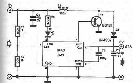
Description: A step-up converter can be designed using the MAX641 integrated circuit from Maxim IC, utilizing a minimal number of electronic components. This high-voltage step-up converter project can deliver a maximum output current of up to 1A. The low battery voltage detector compares the input voltage LB1 with an internal reference of 1.31 V. The LBO output transitions to a low state when the voltage at pin 1 drops below 1.31 V. The threshold voltage for the "low battery" condition is set by a voltage divider formed by resistors R1 and R2.
The MAX641 integrated circuit is a highly efficient solution for applications requiring a boost in voltage. The circuit operates by drawing power from a lower voltage source and converting it to a higher voltage output, making it ideal for battery-powered devices where voltage levels may drop as the battery discharges.
The step-up converter design involves a few key components: the MAX641 IC, input and output capacitors, and the resistors that form the voltage divider. The input capacitor is essential for stabilizing the input voltage and minimizing ripple, while the output capacitor helps smooth the output voltage and maintain a steady current supply.
The voltage divider consisting of resistors R1 and R2 is crucial for setting the low battery detection threshold. When the input voltage (LB1) falls below the reference voltage of 1.31 V, the output at LBO will switch to a low state, signaling that the battery voltage is critically low. This feature is particularly useful for preventing damage to the device from under-voltage conditions and ensuring proper functionality.
In practical applications, the circuit can be implemented on a printed circuit board (PCB) layout, ensuring that all components are placed in a manner that minimizes noise and interference. Proper grounding and decoupling techniques should be employed to enhance the performance of the step-up converter. The design can be further optimized by selecting appropriate values for R1 and R2 to adjust the threshold voltage according to specific requirements.
Overall, the MAX641 step-up converter circuit provides a reliable and efficient solution for applications where increased voltage is necessary while maintaining low power consumption and simple construction.Using MAX641 integrated circuit, manufactured by Maxim IC, can be designed a very simple step-up converter using few electronic components. This step-up high voltage converter electronic projects allows a maximum output current up to 1A. Low battery voltage detector input compare LB1 with internal reference of 1. 31 V. LBO output goes in low state when the voltage at pin 1 falls below 1. 31 V. The threshold voltage for "low battery", is determined by voltage divider R1-R2.
The MAX641 integrated circuit is a highly efficient solution for applications requiring a boost in voltage. The circuit operates by drawing power from a lower voltage source and converting it to a higher voltage output, making it ideal for battery-powered devices where voltage levels may drop as the battery discharges.
The step-up converter design involves a few key components: the MAX641 IC, input and output capacitors, and the resistors that form the voltage divider. The input capacitor is essential for stabilizing the input voltage and minimizing ripple, while the output capacitor helps smooth the output voltage and maintain a steady current supply.
The voltage divider consisting of resistors R1 and R2 is crucial for setting the low battery detection threshold. When the input voltage (LB1) falls below the reference voltage of 1.31 V, the output at LBO will switch to a low state, signaling that the battery voltage is critically low. This feature is particularly useful for preventing damage to the device from under-voltage conditions and ensuring proper functionality.
In practical applications, the circuit can be implemented on a printed circuit board (PCB) layout, ensuring that all components are placed in a manner that minimizes noise and interference. Proper grounding and decoupling techniques should be employed to enhance the performance of the step-up converter. The design can be further optimized by selecting appropriate values for R1 and R2 to adjust the threshold voltage according to specific requirements.
Overall, the MAX641 step-up converter circuit provides a reliable and efficient solution for applications where increased voltage is necessary while maintaining low power consumption and simple construction.Using MAX641 integrated circuit, manufactured by Maxim IC, can be designed a very simple step-up converter using few electronic components. This step-up high voltage converter electronic projects allows a maximum output current up to 1A. Low battery voltage detector input compare LB1 with internal reference of 1. 31 V. LBO output goes in low state when the voltage at pin 1 falls below 1. 31 V. The threshold voltage for "low battery", is determined by voltage divider R1-R2.

Inductorless 3-5 Volts Converter
By configuring a comparator and a transistor to control the oscillator in a charge pump circuit, it is possible to generate a regulated output of virtually any desired value. Charge pump integrated circuits (ICs) can either invert or double an...
12kW PFC Boost Converter
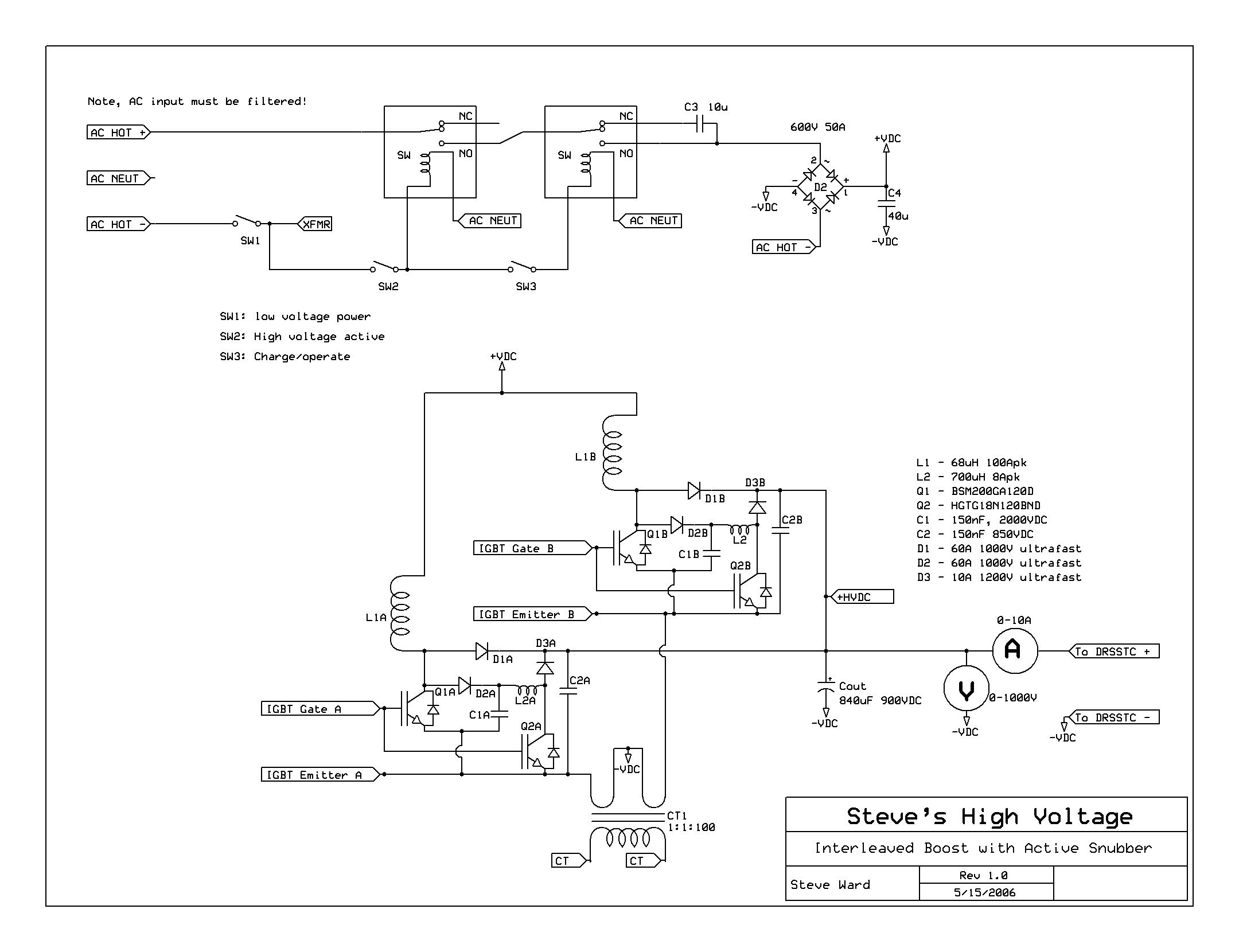
The project is a continuation of the 5kW Boost converter project. After several unsuccessful attempts, the focus shifted towards achieving a higher power level, targeting approximately 10kW. The title was modified from 12kW to 8kW, although the converter is designed...

12V to 3V convertor
A 12V to 3V converter. This is a simple and inexpensive circuit designed to convert voltage from 12V to 3V. In fact, this is a basic regulator circuit.
This 12V to 3V converter circuit typically employs a linear voltage regulator, such...
voltage converter circuit diagram
A substation capable of consuming 100 MVA with 375 kVA, 60 Hz input and 132 kV at 50 Hz using the same power. The challenge is to convert the 60 Hz input to 50 Hz, including a wiring diagram.
To convert...
Step up Voltage converter DC to DC
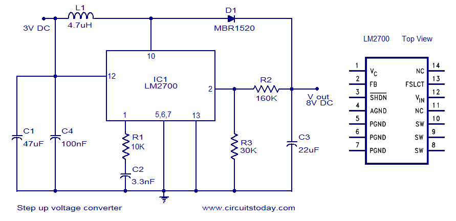
A simple DC to DC step-up voltage converter circuit schematic using the LM2700, which is a step-up switching converter.
The LM2700 is a versatile step-up switching converter designed to efficiently convert a lower input voltage to a higher output voltage. This...

Step-up Converter with LDO Beats SEPIC Efficiency
A step-up converter followed by an LDO regulator provides improved battery life compared to a traditional SEPIC design when powered by a single lithium-ion cell.
The circuit design features a step-up (boost) converter that elevates the input voltage from a single...

Simple Circuit 12V to 120V DC DC Converter
This is a simple circuit designed to convert 12V DC to 120V DC. The circuit comprises two main phases: the inverter stage and the rectifier and filter stage. The NE555 integrated circuit (IC1) is configured as an astable multivibrator, operating...

+5V + 12V boost power supply MAX761
The circuit depicted in the figure illustrates an efficient, low-power step-up DC-DC converter, the MAX761, along with a few external components, which functions as a +5V to +12V boost power supply. Its characteristics include a conversion efficiency of 86% and...

Boost has a frequency characteristic of automatic offset MAX630 power conversion
A low voltage frequency circuit utilizes the MAX630 for low battery voltage detection, functioning as an offset boost converter power supply. It is designed to maintain high efficiency (85%) while providing a DC output voltage of 5V at a current...