


Power-inverter

Description: The transformer can be any 6.3 or 12.6 V type. Apply the 12-V DC input so the positive goes to the transformer's center tap and the negative goes to the two transistor emitters. Any bridge-type rectifier and filter can be used at the output if DC is needed.
In this circuit design, a transformer is utilized to step down or step up the voltage as required, with options for either 6.3 V or 12.6 V types. When implementing the circuit, a 12 V DC input should be connected such that the positive terminal is linked to the center tap of the transformer. This configuration allows for balanced voltage distribution across the secondary winding, which is essential for proper operation of the subsequent components.
The negative terminal of the power supply is connected to the emitters of two transistors, which can be configured in a push-pull arrangement for efficient amplification or switching applications. This setup enables the transistors to operate effectively, driven by the transformer’s output.
For the output stage, a bridge-type rectifier is recommended. This configuration consists of four diodes arranged to convert the alternating current (AC) signal from the transformer into a direct current (DC) signal. The bridge rectifier ensures that both halves of the AC waveform are utilized, resulting in a smoother and more efficient conversion process.
Following the rectifier, a filtering stage is essential to smooth out the pulsating DC output. Various filter designs can be employed, such as capacitive filters, which use capacitors to reduce voltage ripple, or LC filters, which incorporate inductors for further smoothing. The choice of filtering components will depend on the specific application requirements, including the desired output voltage stability and load characteristics.
This circuit configuration is suitable for various applications requiring a reliable DC power source derived from an AC supply, ensuring efficient operation and minimal voltage fluctuations.The transformer can be any 6.3 or 12.6 V type. Apply the 12-Vde input so the positive goes to the transformer"s center tap and the negative goes to the two transistor emitters. Any bridgetype rectifier and filter can be used at the output, if you need de.
In this circuit design, a transformer is utilized to step down or step up the voltage as required, with options for either 6.3 V or 12.6 V types. When implementing the circuit, a 12 V DC input should be connected such that the positive terminal is linked to the center tap of the transformer. This configuration allows for balanced voltage distribution across the secondary winding, which is essential for proper operation of the subsequent components.
The negative terminal of the power supply is connected to the emitters of two transistors, which can be configured in a push-pull arrangement for efficient amplification or switching applications. This setup enables the transistors to operate effectively, driven by the transformer’s output.
For the output stage, a bridge-type rectifier is recommended. This configuration consists of four diodes arranged to convert the alternating current (AC) signal from the transformer into a direct current (DC) signal. The bridge rectifier ensures that both halves of the AC waveform are utilized, resulting in a smoother and more efficient conversion process.
Following the rectifier, a filtering stage is essential to smooth out the pulsating DC output. Various filter designs can be employed, such as capacitive filters, which use capacitors to reduce voltage ripple, or LC filters, which incorporate inductors for further smoothing. The choice of filtering components will depend on the specific application requirements, including the desired output voltage stability and load characteristics.
This circuit configuration is suitable for various applications requiring a reliable DC power source derived from an AC supply, ensuring efficient operation and minimal voltage fluctuations.The transformer can be any 6.3 or 12.6 V type. Apply the 12-Vde input so the positive goes to the transformer"s center tap and the negative goes to the two transistor emitters. Any bridgetype rectifier and filter can be used at the output, if you need de.

A 12V Car Charger For ASUS Eee Notebook
The ASUS Eee is an ultra-portable notebook designed for tech enthusiasts, offering essential features without unnecessary extras. It boasts excellent build quality and is competitively priced. In New Zealand, it can be purchased exclusively from DSE, making it cost-effective compared...
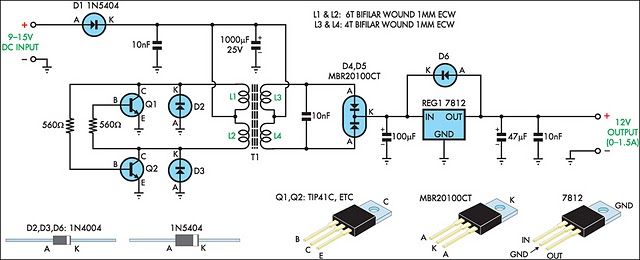
12v regulated inverter supply
When operating 12V electronic devices from lead-acid battery banks, the voltage supplied to the appliance can fluctuate significantly, ranging from below 11V when the batteries are discharged to over 14V during the charging process. Many appliances are not capable of...

Example Transistor Circuit with LEDs
A transistor is an electronic component that allows a small current to control a significantly larger current. This characteristic is valuable in various renewable energy projects and other applications. A basic circuit diagram is provided, featuring a 12V LED spotlight...

Intermittent start and stop cycle control circuit Five of a
The circuit depicted in Figure 3-80 is responsible for controlling a portion of the transistor multivibrator. A multivibrator serves as a robust positive and negative feed-forward amplifier, consisting of two branches that are interconnected through a coupled RC timing circuit,...

NOT circuit
A common-emitter transistor amplifier produces an output signal that is 180 degrees out of phase with the input signal, commonly referred to as an inverting amplifier. When the electrical path for amplifying the pulse signal is activated, this circuit functions...

microcontroller Why this transistor logic as switch is not working
The remote control of an RC car was modified by extending wires from the backward, forward, left, and right switches. Grounding any of these wires completes the circuit and sends a signal to the car. The intention is to close...

Pull transistor relay delay circuit diagrams
The circuit is a relay delay pull transistor configuration. Initially, when powered, the 16 µF capacitor has a voltage of zero, resulting in both transistors being off, and the relay remains inactive. As the 16 µF capacitor charges over time...

transistors Mystery circuit: latching relay control with transitor / capacitor why doesnt it work
A single-coil latching relay is utilized, which can latch and reset with opposite polarities. Testing of the circuit with dual opposite-biased LEDs showed no flickering in either direction, indicating stable charge and discharge behavior. However, there are concerns regarding the...
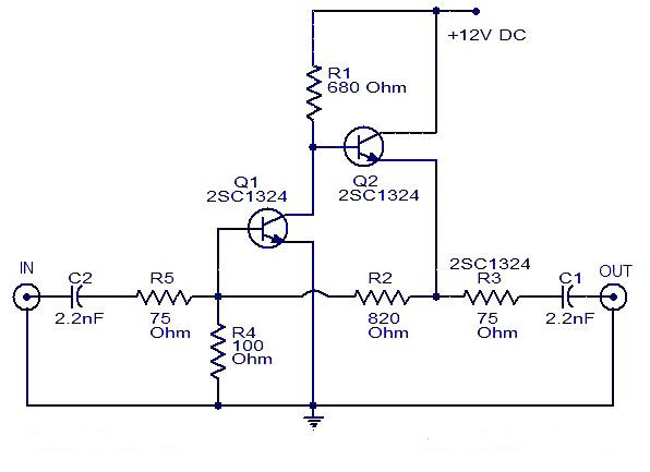
Cable TV amplifier Using 2 Transistor
This is a cable TV amplifier utilizing two transistors. The amplifier circuit is designed for cable TV systems using 75 Ohm coaxial cables and operates effectively up to 150 MHz. Transistor T1 is responsible for amplification, providing an expected gain...