


power supply Why is my simple boost converter giving me such a high peak output voltage
#boost converter
#voltage regulation
#switching frequency
#duty cycle
#power supply
#efficiency
#input current
#output voltage
#ripple
#load current

Description: The supply voltage is 5V, and the goal is to increase it to 12V with a load current of 1A, resulting in an output power of 12W. A switching frequency of 20kHz has been selected, requiring a duty cycle of 0.583, which translates to an on-time of 29.15 µs. Assuming an efficiency of 0.90, the input power will be 13.34W, leading to an input current of 2.67A. The expected voltage at point 2 (between the inductor and the NMOS) is 5V, potentially with a slight ripple, while the voltage at point 3 (between the diode and the capacitor) should be 12V with some ripple. However, the observed output is a peak voltage of 23V oscillating around 11.5V at point 2 and a slightly lower peak voltage of just over 22.5V oscillating around 17V at point 3. Increasing the switching frequency to 200kHz (T=5 µs, Ton=2.915 µs) produced results closer to expectations, with a peak voltage of 12.8V at point 2 (oscillating between that and 0V) and a peak of 12V at point 3 (oscillating around 11.8V), although significant ripple was still present. Increasing the inductor size to 100 µH had minimal effect, primarily affecting startup oscillation. However, increasing the capacitance to 10 µF significantly reduced the voltage oscillation at point 3, as shown in the resultant image with a 10 µF capacitor.
The circuit described is a DC-DC boost converter designed to step up a 5V supply voltage to 12V while delivering a load current of 1A. The converter operates under a switching frequency of 20kHz initially, with a calculated duty cycle of approximately 58.3%, indicating the duration the switch (NMOS transistor) remains on during each cycle. The theoretical on-time of 29.15 µs is critical for achieving the desired output voltage and current.
The input power is calculated based on the efficiency of the converter, which is assumed to be 90%. This results in an input power requirement of 13.34W, leading to an input current of 2.67A. The circuit design anticipates specific voltage levels at two measurement points: point 2, located between the inductor and the NMOS, is expected to show a steady 5V with slight ripple, while point 3, situated between the diode and the output capacitor, should stabilize at 12V with some ripple.
The initial results, however, indicate unexpected behavior, with point 2 showing a peak voltage of 23V and point 3 displaying a peak of over 22.5V. This chaotic output suggests potential issues with the switching frequency or component values. The adjustment of the switching frequency to 200kHz resulted in improved performance, aligning closer to the expected output voltages at both points, albeit with still significant ripple.
The inductor's value was increased to 100 µH in an attempt to stabilize the output, but this change primarily affected startup characteristics without significantly reducing the ripple. A more effective modification was the increase in output capacitance to 10 µF, which effectively minimized the voltage oscillation at point 3, demonstrating the importance of capacitor sizing in filtering output ripple in switching converters.
In summary, the circuit's performance reflects the complexities of switching power supplies, where component selection and operating frequency play crucial roles in achieving stable and efficient voltage conversion. Further refinement of the design may involve optimizing the inductor and capacitor values, as well as fine-tuning the switching frequency to minimize ripple and stabilize output voltages.The supply voltage is 5V and I am seeking to increase it to 12V with a load current of 1A, or an output power of 12W. I selected a switching frequency of 20kHz. By my math, I need a duty cycle of 0. 583 to do this, so the on time should be 29. 15 µs. Assuming an efficiency of 0. 90, the input power will be 13. 34W and the input current 2. 67A. What I expected to see is a voltage of 5V, perhaps with a slight ripple, at point 2 (between the inductor and the NMOS) and a voltage of 12V with a ripple at point 3 (between the diode and the capacitor). Instead, what comes out is what looks like total chaos - I get a peak voltage of 23V that oscillates around 11.
5V at point 2 and a slightly lower peak voltage of just over 22. 5V that oscillates around 17V at point 3: On the hunch that my switching frequency might be too low, I tried increasing it to 200kHz (T=5 µs, Ton=2. 915 µs) and now I get something more like what I was looking for, which is a peak voltage of 12. 8V at point 2 (oscillating between that and 0V) and a peak of 12V at point 3 (oscillating about 11. 8V): There was significant ripple in the voltage. I tried increasing the size of the inductor to 100 µH but all it seemed to affect was the startup oscillation.
So I increased the capacitance to 10 µF, and that seemed to work, the voltage oscillation at point 3 is much smaller. The image above is the result with a 10 µF capacitor.
The circuit described is a DC-DC boost converter designed to step up a 5V supply voltage to 12V while delivering a load current of 1A. The converter operates under a switching frequency of 20kHz initially, with a calculated duty cycle of approximately 58.3%, indicating the duration the switch (NMOS transistor) remains on during each cycle. The theoretical on-time of 29.15 µs is critical for achieving the desired output voltage and current.
The input power is calculated based on the efficiency of the converter, which is assumed to be 90%. This results in an input power requirement of 13.34W, leading to an input current of 2.67A. The circuit design anticipates specific voltage levels at two measurement points: point 2, located between the inductor and the NMOS, is expected to show a steady 5V with slight ripple, while point 3, situated between the diode and the output capacitor, should stabilize at 12V with some ripple.
The initial results, however, indicate unexpected behavior, with point 2 showing a peak voltage of 23V and point 3 displaying a peak of over 22.5V. This chaotic output suggests potential issues with the switching frequency or component values. The adjustment of the switching frequency to 200kHz resulted in improved performance, aligning closer to the expected output voltages at both points, albeit with still significant ripple.
The inductor's value was increased to 100 µH in an attempt to stabilize the output, but this change primarily affected startup characteristics without significantly reducing the ripple. A more effective modification was the increase in output capacitance to 10 µF, which effectively minimized the voltage oscillation at point 3, demonstrating the importance of capacitor sizing in filtering output ripple in switching converters.
In summary, the circuit's performance reflects the complexities of switching power supplies, where component selection and operating frequency play crucial roles in achieving stable and efficient voltage conversion. Further refinement of the design may involve optimizing the inductor and capacitor values, as well as fine-tuning the switching frequency to minimize ripple and stabilize output voltages.The supply voltage is 5V and I am seeking to increase it to 12V with a load current of 1A, or an output power of 12W. I selected a switching frequency of 20kHz. By my math, I need a duty cycle of 0. 583 to do this, so the on time should be 29. 15 µs. Assuming an efficiency of 0. 90, the input power will be 13. 34W and the input current 2. 67A. What I expected to see is a voltage of 5V, perhaps with a slight ripple, at point 2 (between the inductor and the NMOS) and a voltage of 12V with a ripple at point 3 (between the diode and the capacitor). Instead, what comes out is what looks like total chaos - I get a peak voltage of 23V that oscillates around 11.
5V at point 2 and a slightly lower peak voltage of just over 22. 5V that oscillates around 17V at point 3: On the hunch that my switching frequency might be too low, I tried increasing it to 200kHz (T=5 µs, Ton=2. 915 µs) and now I get something more like what I was looking for, which is a peak voltage of 12. 8V at point 2 (oscillating between that and 0V) and a peak of 12V at point 3 (oscillating about 11. 8V): There was significant ripple in the voltage. I tried increasing the size of the inductor to 100 µH but all it seemed to affect was the startup oscillation.
So I increased the capacitance to 10 µF, and that seemed to work, the voltage oscillation at point 3 is much smaller. The image above is the result with a 10 µF capacitor.
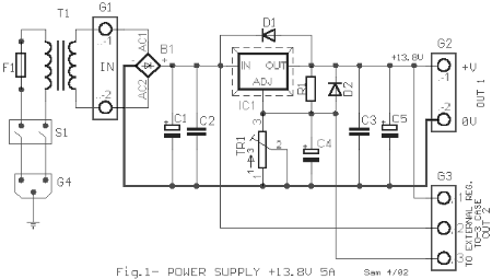
Circuit diagrams and Schematic
This AC to DC power supply can output 5A in continuous operation and 12A peak current. This type of DC power supply uses a PCB, allowing for two case types for IC1: TO-220 or TO-3. The regulation of this 12-volt...

filtering noisy power signal
Previously, a linear regulator was used, but a Max756 boost converter is now in operation. An output ripple of 0.1 to 0.3V is observed in the current, while the Max756 datasheet indicates an expected ripple of about 50 mA. Although...
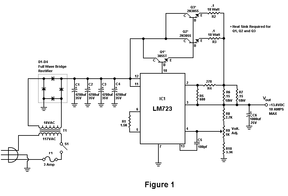
Build A 10 Amp 13.8 Volt Power Supply
Sometimes amateurs like to home-brew their power supplies instead of purchasing one off the shelf at any of the major ham radio retail dealers. The advantage to rolling your own power supply is that it teaches us how they work...

Panasonic M12H switching power supply circuit diagram
The Panasonic M12H switching power supply circuit is utilized in Panasonic models such as TC-230H, TC-2030DHN, TC-830D, and TC-840D. The circuit operates with an oscillation frequency that generates approximately 300V DC voltage at C836. The T801 transformer is involved in...

Switching power supply monolithic switching regulator DN-25 configuration
As shown in the figure, the DN-25 IC is a switching power supply. The DN-25 is a monolithic switching power supply device suitable for medium output current applications and a wide voltage range. Its main performance indicators include an input...

Sony KV-S29MHl TV switching power supply (SIR a 80145A) circuit diagram
The circuit of the Sony KV-S29MHl (S Movement series) TV switching power supply (SIR a 80145A) consists of three main sections: (A) the power oscillation part, (B) the regulator part, and (C) the output section.
The Sony KV-S29MHl TV switching power...

Power Supply 0-30V / 0-2A
The basic requirements for a laboratory power supply are to provide the necessary voltages and currents with low output resistance, low noise, minimal ripple, and good stabilization. These requirements are addressed within the circuit design. Many power supplies incorporate electronic...

Duty Cycle Selector
The Duty Cycle Selector is a unique project designed to select the duty cycle in 9 steps up to 100%. It includes a circuit diagram and a description of the duty cycle selector and various digital circuits.
The Duty Cycle Selector...

100v / 10ma regulator circuit
The circuit features no-load and short circuit protection mechanisms. To accommodate short circuit conditions, it is necessary to increase resistors R1 and R2 to allow for power dissipation; for example, R1 can be set to 1.2kΩ with a power rating...