


PUSH-PULL DC-AC INVERTER

Description: This project originated as a request from a paying customer and has demonstrated several advantages over previous similar designs. It functions primarily as an inverter, converting 12V DC power into various outputs. The circuit can convert 12V DC to either 230V AC (or 117V AC) or 24V DC. The AC output can deliver approximately 30 Watts, sufficient to power three medium-sized 11W economy lamps or about eight 4W lamps, each providing equivalent light to a 20W bulb. Additionally, the output can be rectified to obtain 250V DC for powering valve equipment. The DC-AC version can also be adapted to generate 6V AC, along with 230V DC for portable operation of vintage valve-based equipment. For instance, an EL84 can provide over 10 Watts of RF in the HF band, maintaining efficiency comparable to transistor devices, with a heated cathode consuming just 2 Watts. The 12V DC, 24V DC, or -12V DC configurations can deliver approximately 3 Amperes at 24V (65 Watts) or -12V (32 Watts). This is achieved by converting 12V DC to 12V AC, full-wave rectifying the output, and placing the new isolated 12V DC in series with the input 12V DC, resulting in 24V DC at 3 Amperes for 6 Amperes input. Reversing the diodes and referencing the rectifier to ground yields -12V at about 3 Amperes for a 3 Amperes input. As a DC-AC converter, the output frequency accuracy is sufficient to operate a clock radio for short durations without significant time drift. Selecting stable capacitors and careful frequency adjustments can achieve accuracy better than 0.1%. The core of the waveform generator utilizes the CD4060, functioning as a free-running astable oscillator and divider. The output is extracted from Q8, resulting in the oscillator being divided by 2 a total of eight times, yielding a total divide rate of 256. For a 60Hz output, the oscillator is set to 15,360Hz (60Hz x 256), while for a 50Hz output, it is set to 12,800Hz (50Hz x 256). Capacitor C2 should be a 2.2nF (2200pF) mylar type or a stable polystyrene type, as ceramic capacitors are unsuitable. The resistor marked Rx consists of three series resistors, which must be selected to achieve the desired frequency. A frequency counter is essential for this process; if unavailable, frequency comparison with the mains using a dual-trace oscilloscope can be utilized. The CD4060 operates from a 5V DC supply derived from a 78L05 regulator chip, which is vulnerable to high supply voltage. To protect it, a resistor is placed in series with the input supply, allowing the resistor to dissipate some power and safeguard the regulator. For frequency adjustment, initial prototypes utilized different resistor combinations, and the frequency can be measured and adjusted accordingly. The output of the CD4060 (Q8) is buffered by an NPN general-purpose transistor (TR1) and inverted by a second transistor (TR2), producing two separate square waves that are in anti-phase. Additional transistors (TR3a, TR4a, TR5a, TR3b, TR4b, and TR5b) are configured as cascaded common-emitter power inverters driven from phase-a.
The schematic design of this inverter circuit incorporates several key components, including the CD4060, which serves as the primary oscillator. The output from the oscillator is carefully buffered and inverted to create the necessary waveforms for driving the power transistors. The selection of stable capacitors and resistors is crucial for maintaining frequency accuracy and ensuring reliable operation. The power transistors are arranged in a push-pull configuration to effectively drive the output load, whether it be AC or DC. The use of a frequency counter or oscilloscope is recommended for fine-tuning the oscillator frequency, ensuring that the output remains stable and within acceptable limits for the intended application. The overall design emphasizes efficiency and versatility, making it suitable for various power conversion tasks, from lighting applications to vintage audio equipment. Proper thermal management and component selection will enhance the longevity and reliability of the circuit, particularly in demanding environments.This turned out to be quite an interesting project. It all began as a project for a paying customer, but I found that the circuit had quite a lot of advantages over previous similar projects. It is basically an inverter for converting power from 12v DC to something else. You can use the circuit as shown to convert 12v DC to 230v AC (117v AC), or even use it to convert 12v DC to 24v DC. The output power of the AC version is about 30 Watts, which is enough to power three medium sized (11W) ecconomy lamps, or about 8 of those small 4W lamps that each give the same light as a 20-Watt lamp. You could even rectify the output to get 250vDC to power valve equipment. The DC-AC version can be adapted to generate 6vAC, in addition to 230v DC for portable operation of old valve (tube) based equipment.
An EL84, for example, will deliver over 10 Watts of RF in the HF band, and the efficiency is still comparable with transistor devices. The heated cathode takes just 2 Watts. The 12vDC 24vDC or -12vDC configuration will deliver about 3 Amperes at 24v 65 Watts, or -12v 32 Watts.
To do this you convert 12vDC to 12vAC, full-wave rectify this and put the new isolated 12vDC in series with the input 12vDC. Your output will then be 24vDC at 3 Amperes, for 6 Amperes input. Reverse the diodes and reference the rectifier to ground and you will get -12v at about 3 Amperes for 3 Amperes input.
See below: But as a DC-AC converter, the output frequency accuracy is good enought to run a clock-radio for a short duration of time, without gaining or loosing more than a few seconds per day. The important bit is that you choose stable capacitors and take care to get the frequency right. You should be able to get it better than 0. 1% with just a little effort. The heart of the waveform generator is the CD4060, which is used as a free-running astable oscillator and divider.
The output is taken from Q8, which means the oscillator is succesively divided by 2, eight times. Total divide rate is 256. If you want to generate 60Hz then the the oscillator is adjusted to 60Hz x 256 = 15, 360Hz. If you want 50Hz then set the oscillator to 50Hz x 256 = 12, 800Hz. The capacitor C2 is a 2. 2nf (2200pf) mylar type. You can also use a 2200pf polystyrene type. The important thing is that you use a stable cap here. Ceramic capacitors cannot be used. The resistor marked Rx on the circuit is composed of three resistors in series. These you must select to get the correct frequency. A frequency counter is essential here. If you do not have a counter, then you can compare the frequency with your mains frequency using a dual-trace oscilloscope. You should be able to get the two traces to remain stationary. If you couple a counter to the oscillator you will alter the frequency, so instead couple the counter to the CD4060 pin 7 (Q4) and select the resistors for 800Hz (50Hz), or 960Hz (60Hz).
The CD4060 is powered from 5vDC which is derived from a 78L05 regulator chip. I have managed to blow up these devices! The output is protected, but if you have too high supply voltage then they do get a bit hot. I therefore tend to use a resistor in series with the input supply so the cheap resistor burns a few mW of power, thus saving my 78L05 from an excessive input voltage. See R1 in the circuit diagram. In my first prototype the resistors for 60Hz were 10K + 1K0 + 180 Ohms (11, 180 Ohms). In my second prototype I needed 10K + 3K9 + 680 Ohms = 14, 580 Ohms. The thing to do is to put in there a 10K resistor and measure the frequency and resistor value. If you get 1036Hz and the resistor is 9. 97K, then use the formulas: The output of the CD4060 (Q8) is buffered by an NPN general-purpose transistor, TR1, and inverted by the second transistor TR2.
This gives us two seperate square-waves that are in anti-phase. TR3a, TR4a and TR5a are cascaded common-emitter power inverters driven from phase-a. TR3b, TR4b and TR5b are cascaded common-emitt
The schematic design of this inverter circuit incorporates several key components, including the CD4060, which serves as the primary oscillator. The output from the oscillator is carefully buffered and inverted to create the necessary waveforms for driving the power transistors. The selection of stable capacitors and resistors is crucial for maintaining frequency accuracy and ensuring reliable operation. The power transistors are arranged in a push-pull configuration to effectively drive the output load, whether it be AC or DC. The use of a frequency counter or oscilloscope is recommended for fine-tuning the oscillator frequency, ensuring that the output remains stable and within acceptable limits for the intended application. The overall design emphasizes efficiency and versatility, making it suitable for various power conversion tasks, from lighting applications to vintage audio equipment. Proper thermal management and component selection will enhance the longevity and reliability of the circuit, particularly in demanding environments.This turned out to be quite an interesting project. It all began as a project for a paying customer, but I found that the circuit had quite a lot of advantages over previous similar projects. It is basically an inverter for converting power from 12v DC to something else. You can use the circuit as shown to convert 12v DC to 230v AC (117v AC), or even use it to convert 12v DC to 24v DC. The output power of the AC version is about 30 Watts, which is enough to power three medium sized (11W) ecconomy lamps, or about 8 of those small 4W lamps that each give the same light as a 20-Watt lamp. You could even rectify the output to get 250vDC to power valve equipment. The DC-AC version can be adapted to generate 6vAC, in addition to 230v DC for portable operation of old valve (tube) based equipment.
An EL84, for example, will deliver over 10 Watts of RF in the HF band, and the efficiency is still comparable with transistor devices. The heated cathode takes just 2 Watts. The 12vDC 24vDC or -12vDC configuration will deliver about 3 Amperes at 24v 65 Watts, or -12v 32 Watts.
To do this you convert 12vDC to 12vAC, full-wave rectify this and put the new isolated 12vDC in series with the input 12vDC. Your output will then be 24vDC at 3 Amperes, for 6 Amperes input. Reverse the diodes and reference the rectifier to ground and you will get -12v at about 3 Amperes for 3 Amperes input.
See below: But as a DC-AC converter, the output frequency accuracy is good enought to run a clock-radio for a short duration of time, without gaining or loosing more than a few seconds per day. The important bit is that you choose stable capacitors and take care to get the frequency right. You should be able to get it better than 0. 1% with just a little effort. The heart of the waveform generator is the CD4060, which is used as a free-running astable oscillator and divider.
The output is taken from Q8, which means the oscillator is succesively divided by 2, eight times. Total divide rate is 256. If you want to generate 60Hz then the the oscillator is adjusted to 60Hz x 256 = 15, 360Hz. If you want 50Hz then set the oscillator to 50Hz x 256 = 12, 800Hz. The capacitor C2 is a 2. 2nf (2200pf) mylar type. You can also use a 2200pf polystyrene type. The important thing is that you use a stable cap here. Ceramic capacitors cannot be used. The resistor marked Rx on the circuit is composed of three resistors in series. These you must select to get the correct frequency. A frequency counter is essential here. If you do not have a counter, then you can compare the frequency with your mains frequency using a dual-trace oscilloscope. You should be able to get the two traces to remain stationary. If you couple a counter to the oscillator you will alter the frequency, so instead couple the counter to the CD4060 pin 7 (Q4) and select the resistors for 800Hz (50Hz), or 960Hz (60Hz).
The CD4060 is powered from 5vDC which is derived from a 78L05 regulator chip. I have managed to blow up these devices! The output is protected, but if you have too high supply voltage then they do get a bit hot. I therefore tend to use a resistor in series with the input supply so the cheap resistor burns a few mW of power, thus saving my 78L05 from an excessive input voltage. See R1 in the circuit diagram. In my first prototype the resistors for 60Hz were 10K + 1K0 + 180 Ohms (11, 180 Ohms). In my second prototype I needed 10K + 3K9 + 680 Ohms = 14, 580 Ohms. The thing to do is to put in there a 10K resistor and measure the frequency and resistor value. If you get 1036Hz and the resistor is 9. 97K, then use the formulas: The output of the CD4060 (Q8) is buffered by an NPN general-purpose transistor, TR1, and inverted by the second transistor TR2.
This gives us two seperate square-waves that are in anti-phase. TR3a, TR4a and TR5a are cascaded common-emitter power inverters driven from phase-a. TR3b, TR4b and TR5b are cascaded common-emitt

PERIOD TO VOLTAGE CONVERTER
When the input transitions from low to high, a narrow positive pulse is generated at point A. This pulse results in a -13 V level at point B, which causes diode D2 to turn off. Consequently, the V+ voltage of...
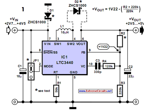
Buck-Boost Voltage Converter
Sometimes it is necessary to power a circuit from a battery where the required supply voltage falls within the discharge curve of the battery. If the battery...
Powering a circuit from a battery involves understanding the discharge characteristics of the battery...

12V to 9 or 6 v converter
This circuit allows transistorized devices, such as radios, cassette players, and other electrical appliances, to operate from a car's electrical supply. The accompanying table provides resistor values and specifies diode types for different voltage levels. If multiple voltage levels are...

Job Analysis push-pull output
A, B, and C represent indirect person capacitance. The new access capacitor C is known as the bootstrap capacitor. The self-bootstrap capacitor can increase the voltage at point A. When static, Vi = 0V, the midpoint voltage VD is V...

Voltage Converter 3V to 5V using MAX660
Voltage converter circuit diagram for converting 3 volts to 5 volts using CMOS monolithic ICs MAX660 and MAX667, which functions as a positive voltage regulator.
The voltage converter circuit utilizes the MAX660 and MAX667 integrated circuits to step up a 3-volt...

12vdc 220vac inverter
This circuit inverter converts a 12V DC battery to 220V AC, serving as a replacement for home energy. The inverter can power small electronic devices such as lamps, radios, phone chargers, and disc players. The central component of the inverter...
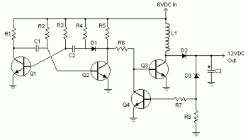
6vdc to 12vdc converter circuit
Various values of D3 can be utilized to achieve different output voltages ranging from approximately 0.6V to around 30V. It is important to note that at elevated voltages, the circuit's performance may diminish, potentially resulting in lower current output. Additionally,...
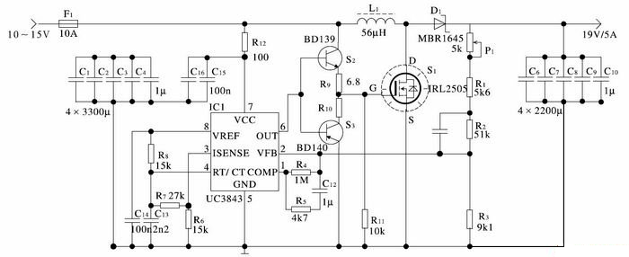
notebook power car adapter 19 volt
The car cigarette lighter outputs a DC voltage of 12 V, which does not exceed 13.8 V even when the engine is running. A voltage of 19 V is lower than the normally required levels.
The car cigarette lighter circuit is...

12V to 6V Converter
This small but useful circuit is a DC voltage converter for using 6V devices with car battery voltage. The maximum output current is dependent if the T1 is covered with a proper heat sink or not. You can use the...