


Single-ended forward converter circuit
#forward converter
#humidity sensor
#frequency conversion
#integrating circuit
#capacitive sensor
#signal conversion
#power electronics
#circuit design

Description: The humidity/frequency conversion circuit operates similarly to the previously mentioned humidity sensors. At a humidity level of 76%, the equivalent capacitance is 500 pF, with a capacitive relative humidity variation rate of +1.7 pF/%. The circuit includes an integrating circuit (A1), which is proportional to the integral current humidity. A reference voltage generating circuit (A2) and a comparison circuit (A3) are also part of the design. When pin 16 of the LTC1043 is inactive, the internal clock operates at approximately 150 kHz. Pins 2 and 6 are shorted, allowing the humidity capacitance (C) to charge with a negative voltage. When pins 2 and 5 are shorted, the current flows into the inverting input of A1, causing the output voltage to rise, resulting in a stepped waveform at A1's output.
At 0% RH, the humidity capacitance (C) is not zero, necessitating compensation through the switched capacitors at pins 7, 8, 12, 13, 11, and 14. As A2 inverts the signal, a positive voltage is applied to the inverting input of A3, where A2 connects to the inverting input of the switched capacitor resistors for temperature compensation. Capacitors C6 (330 pF), C4 (470 pF), and C5 (0.01 µF) are selected to have the same temperature coefficient, ensuring they remain unaffected by temperature changes, similar to the humidity capacitance (C).
The voltage at A3's inverting input remains constant. If the stepped waveform output voltage from A1 is lower than this inverting input voltage, A3's output is low; if higher, the output is high. The discharge through VT and C5 is inversely proportional to the timing of each step from the initial state to the increased size of the stepped waveform from C5. This process corresponds to a clock pulse period that is proportional to the charge accumulated in the humidity capacitor (C), which is inversely proportional to the capacitance.
The process is repeated until the stepped waveform output voltage from A1 equals the inverting input voltage of A3, resulting in an output pulse from A3. The pulse duration is inversely proportional to the humidity capacitance, which in turn affects the frequency and capacity. The first adjustment of RP1 (10 kΩ) sets the output signal frequency to 50 Hz at 5% RH, followed by the adjustment of potentiometer RP2 (20 kΩ) to achieve a frequency of 900 Hz at 90% RH. Once calibrated, the circuit provides an output signal frequency ranging from 0 to 1000 Hz for humidity levels of 0 to 100% RH, with an accuracy of 2%.
The schematic of the humidity/frequency conversion circuit illustrates the integration of various components, including the LTC1043, capacitors, and resistors, to achieve precise humidity measurement and conversion into frequency signals. The design emphasizes stability and accuracy across a wide range of humidity levels, making it suitable for applications requiring reliable humidity monitoring.FIG humidity / frequency conversion circuit. The same as the above humidity sensors, humidity 76% isochronous The equivalent capacitance of 500pF, capacitive relative humidity variation rate was +1.7 pF /%. Circuits, A1 is the integrating circuit, which is proportional to the integral current humidity. A reference voltage generating circuit A2, A3 is a comparison circuit. When the LTC1043 16 feet off, the internal clock circuit, the operating frequency of about 150 kHz. 2 feet and 6 feet short, humidity capacitance C with a negative voltage charge. When 2 feet and 5 feet short, the current flowing into the inverting input of A1, the output voltage rises. Repeat the above process, A1 output is stepped wave voltage. In fact, when the humidity is 0% RH, humidity capacitance capacitor C is not zero, so to compensate, and 7,8 and 12, 13 and 11 feet and 14 feet of the switched capacitor is set for this.
Since the effect of A2 is inverted, a positive voltage is applied to the inverting input terminal of the A3, A2 corresponds to the inverting input of the switched capacitor resistors, for temperature compensation. As the capacitor C6 (330pF), the capacitor C4 (470 pF), and a capacitor C5 (0.01 F) is the same as the temperature coefficient, hence, are not affected by temperature changes.
In addition, humidity capacitance C capacity is not affected by temperature changes. Since A3 inverting input voltage constant, if the step wave output voltage A1 is less than the inverting input voltage, A3 output is low; if higher than the inverting input voltage, the output is high A3, VT guide pass, C5 through VT discharge, discharge voltage is inversely proportional to each step of the ending time from the start state to C5 stepped wave of increased size. This is equivalent to a clock pulse period proportional to the charge accumulated in the capacitor C in humidity, that is inversely proportional to the capacitance.
Repeat the above process, step wave output voltage A1 inverting input voltage equal to A3, A3 output pulse. Pulse duration is inversely proportional to the capacitance humidity, which is inversely proportional to frequency and capacity.
First adjust RP1 (10 k ), so that the humidity of 5% RH output signal frequency of 50 Hz; then adjust potentiometer RP2 (20 k ), so that the humidity of the output signal frequency of 90% RH to 900 Hz. After all adjusted, when the humidity is 0 ~ i00% RH, the output signal frequency is 0 ~ 1000 Hz, 2% accuracy.
FIG humidity / frequency conversion circuit
At 0% RH, the humidity capacitance (C) is not zero, necessitating compensation through the switched capacitors at pins 7, 8, 12, 13, 11, and 14. As A2 inverts the signal, a positive voltage is applied to the inverting input of A3, where A2 connects to the inverting input of the switched capacitor resistors for temperature compensation. Capacitors C6 (330 pF), C4 (470 pF), and C5 (0.01 µF) are selected to have the same temperature coefficient, ensuring they remain unaffected by temperature changes, similar to the humidity capacitance (C).
The voltage at A3's inverting input remains constant. If the stepped waveform output voltage from A1 is lower than this inverting input voltage, A3's output is low; if higher, the output is high. The discharge through VT and C5 is inversely proportional to the timing of each step from the initial state to the increased size of the stepped waveform from C5. This process corresponds to a clock pulse period that is proportional to the charge accumulated in the humidity capacitor (C), which is inversely proportional to the capacitance.
The process is repeated until the stepped waveform output voltage from A1 equals the inverting input voltage of A3, resulting in an output pulse from A3. The pulse duration is inversely proportional to the humidity capacitance, which in turn affects the frequency and capacity. The first adjustment of RP1 (10 kΩ) sets the output signal frequency to 50 Hz at 5% RH, followed by the adjustment of potentiometer RP2 (20 kΩ) to achieve a frequency of 900 Hz at 90% RH. Once calibrated, the circuit provides an output signal frequency ranging from 0 to 1000 Hz for humidity levels of 0 to 100% RH, with an accuracy of 2%.
The schematic of the humidity/frequency conversion circuit illustrates the integration of various components, including the LTC1043, capacitors, and resistors, to achieve precise humidity measurement and conversion into frequency signals. The design emphasizes stability and accuracy across a wide range of humidity levels, making it suitable for applications requiring reliable humidity monitoring.FIG humidity / frequency conversion circuit. The same as the above humidity sensors, humidity 76% isochronous The equivalent capacitance of 500pF, capacitive relative humidity variation rate was +1.7 pF /%. Circuits, A1 is the integrating circuit, which is proportional to the integral current humidity. A reference voltage generating circuit A2, A3 is a comparison circuit. When the LTC1043 16 feet off, the internal clock circuit, the operating frequency of about 150 kHz. 2 feet and 6 feet short, humidity capacitance C with a negative voltage charge. When 2 feet and 5 feet short, the current flowing into the inverting input of A1, the output voltage rises. Repeat the above process, A1 output is stepped wave voltage. In fact, when the humidity is 0% RH, humidity capacitance capacitor C is not zero, so to compensate, and 7,8 and 12, 13 and 11 feet and 14 feet of the switched capacitor is set for this.
Since the effect of A2 is inverted, a positive voltage is applied to the inverting input terminal of the A3, A2 corresponds to the inverting input of the switched capacitor resistors, for temperature compensation. As the capacitor C6 (330pF), the capacitor C4 (470 pF), and a capacitor C5 (0.01 F) is the same as the temperature coefficient, hence, are not affected by temperature changes.
In addition, humidity capacitance C capacity is not affected by temperature changes. Since A3 inverting input voltage constant, if the step wave output voltage A1 is less than the inverting input voltage, A3 output is low; if higher than the inverting input voltage, the output is high A3, VT guide pass, C5 through VT discharge, discharge voltage is inversely proportional to each step of the ending time from the start state to C5 stepped wave of increased size. This is equivalent to a clock pulse period proportional to the charge accumulated in the capacitor C in humidity, that is inversely proportional to the capacitance.
Repeat the above process, step wave output voltage A1 inverting input voltage equal to A3, A3 output pulse. Pulse duration is inversely proportional to the capacitance humidity, which is inversely proportional to frequency and capacity.
First adjust RP1 (10 k ), so that the humidity of 5% RH output signal frequency of 50 Hz; then adjust potentiometer RP2 (20 k ), so that the humidity of the output signal frequency of 90% RH to 900 Hz. After all adjusted, when the humidity is 0 ~ i00% RH, the output signal frequency is 0 ~ 1000 Hz, 2% accuracy.
FIG humidity / frequency conversion circuit

Relative humidity digitizer circuit diagram
The output DC voltage of sensor SEN1 changes linearly in response to variations in relative humidity. This DC voltage is routed through resistors R1 and R2 to the analog-to-digital (A/D) converter chip U2. Resistor R4 is connected to ground, while...
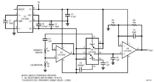
Humidty Sensor To Data Aquisition System Interface
The circuit depicted in the schematic utilizes zero-drift operational amplifiers (LTC1250 and LTC1050) along with a precision instrumentation switched capacitor block (LTC1043). This design achieves exceptional DC accuracy down to microvolt levels. The choice of this method over a true...
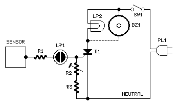
Mains-operated Capacitive Sensor
This very simple circuit acts as a high sensitivity capacitive sensor. Lamps and/or Buzzers are operated at half the mains supply voltage when a part of the human body comes in contact with the sensor or approaches it at a...
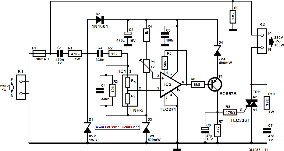
Automatic Air Humidifier
The humidifier circuit is based on a specific humidity sensor, Type NH-3 from Figaro. The circuit controls a ventilator that is part of an air humidifying system, depending on the sensor output. A triac is used to switch the ventilator...

Low humidity is a circuit diagram of CGS-H ceramic humidity sensor configuration
CGS-H ceramic humidity sensor constructed low humidity detection circuit diagram.
The CGS-H ceramic humidity sensor is designed to detect low humidity levels within a specified range. This sensor operates on the principle of changes in capacitance that occur with variations in...
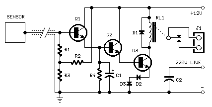
Capacitive Sensor
Q1, Q2, and Q3 form a high-impedance super-Darlington configuration that drives the relay, amplifying the 50 or 60 Hz alternating mains supply frequency induced in the sensor by the human body. Capacitors C1, D2, and D3 ensure clean switching of...
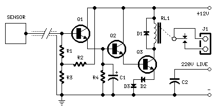
Capacitive Sensor
The purpose of this circuit is to animate shop-windows by means of a capacitive sensor placed behind a post-card-like banner. The card is placed against the glass inside the shop-window, and the visitor can activate the relay placing his hand...

case stepper
Beige Bag Software has been offering affordable and innovative circuit design tools since 1990. B2 Spice provides schematics as well as analog, digital, and mixed-mode electronic circuit simulation. It integrates with EAGLE and CADSTAR PCB software.
B2 Spice is a powerful...

Use Analog Techniques To Measure Capacitance In Capacitive Sensors
Capacitive sensors are utilized in various devices, ranging from consumer electronics to industrial and process control systems. Touch buttons are increasingly integrated into lamps and dimmers, while motion detectors can sense minute changes in deflection. Hygrometers measure humidity levels, and...